DYNAMIC TORQUE CONTROL 4WD/AWD SYSTEM TERMINALS OF ECU
 |
09843-18040 | Diagnosis Check Wire No. 2 |
-
CHECK 4WD ECU ASSEMBLY
-
Measure the voltage and resistance of the connector.
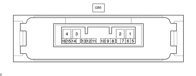
Terminal No. (Symbol) Wiring Color Terminal Description Condition Specified Condition G86-10 (4WDS) - G86-4 (GND) R - W-B 4WD/AWD lock switch signal Ignition switch ON
4WD/AWD lock switch OFF → ON
11 to 14 V → Below 1 V G86-11 (EXI)* - G86-4 (GND) GR - W-B Sport mode switch signal Ignition switch ON
Sport mode switch OFF → ON
11 to 14 V → Below 1 V G86-6 (CANH) - G86-5 (CANL) L - W HIGH-level CAN bus wire - LOW-level CAN bus wire Cable disconnected from negative (-) battery terminal 54 to 69 Ω G86-4 (GND) - Body ground W-B - Body ground Ground Always Below 1 Ω G86-3 (IG1) - G86-4 (GND) V - W-B Power source voltage Ignition switch ON 11 to 14 V G86-2 (SLC+) - G86-1 (SLC-) W - B 4WD linear solenoid signal D position, Idling Pulse generation (See waveform 1)
-
*: for Manual Transaxle w/ Sport Mode
If the result is not as specified, the 4WD ECU assembly may have a malfunction.
-
-
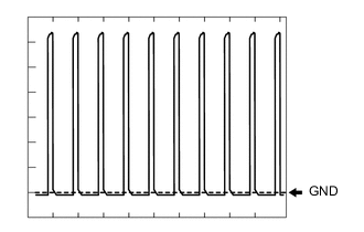
Using an oscilloscope, check the waveform 1.
Waveform 1 (Reference) Item Content Terminal No. (Symbol) G86-2 (SLC+) - G86-1 (SLC-) Tester Range 2 V/DIV., 1 msec./DIV. Condition D position, Idling
-