PARK / NEUTRAL POSITION SWITCH INSTALLATION
PROCEDURE
-
INSTALL PARK/NEUTRAL POSITION SWITCH ASSEMBLY
-
Temporarily install the park/neutral position switch assembly to the continuously variable transaxle assembly with the 2 bolts.
-
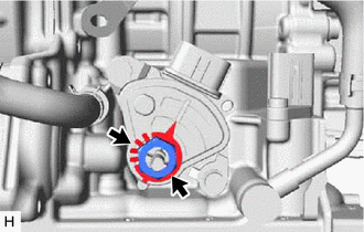
Install the lock plate and lock nut to the park/neutral position switch assembly.
- Torque:
- 6.9 N*m { 70 kgf*cm, 61 in.*lbf }
-
Temporarily install the control shaft lever to the park/neutral position switch assembly.
-
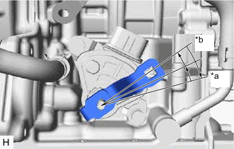
*a P Position *b N Position Turn the control shaft lever clockwise until it stops, then turn it counterclockwise 2 notches.
-
Remove the control shaft lever from the park/neutral position switch assembly.
-
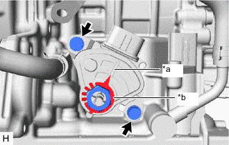
*a Neutral Basic Line *b Protrusion Align the protrusion with the neutral basic line.
-
Hold the park/neutral position switch assembly in that position and tighten the 2 bolts.
- Torque:
- 5.4 N*m { 55 kgf*cm, 48 in.*lbf }
-
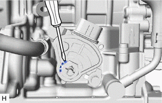
Using a screwdriver, stake the lock nut with the lock plate.
-
Install the control shaft lever to the park/neutral position switch assembly with the washer and nut.
- Torque:
- 12.7 N*m { 130 kgf*cm, 9 ft.*lbf }
-
Connect the park/neutral position switch assembly connector.
-
-
CONNECT TRANSMISSION CONTROL CABLE ASSEMBLY
-
Connect the transmission control cable assembly to the No. 1 transmission control cable bracket with a new clip.
-
*a P Position *b N Position Turn the control shaft lever clockwise until it stops, then turn it counterclockwise 2 notches.
-
Connect the transmission control cable assembly to the control shaft lever with the nut.
- Torque:
- 12 N*m { 122 kgf*cm, 9 ft.*lbf }
-
-
INSPECT SHIFT LEVER POSITION
-
ADJUST SHIFT LEVER POSITION
-
INSPECT PARK/NEUTRAL POSITION SWITCH ASSEMBLY OPERATION
-
ADJUST PARK/NEUTRAL POSITION SWITCH ASSEMBLY
-
INSTALL NO. 1 ENGINE UNDER COVER