OIL COOLER INSTALLATION
PROCEDURE
-
INSTALL OIL COOLER
-
Install the oil cooler to the continuously variable transaxle assembly with the 3 bolts.
- Torque:
- 13.5 N*m { 138 kgf*cm, 10 ft.*lbf }
-
-
INSTALL NO. 1 OIL COOLER INLET HOSE AND NO. 1 OIL COOLER OUTLET HOSE
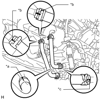
*a White Paint Mark *b Yellow Paint Mark *c Pink Paint Mark
-
Connect the 2 oil cooler hoses to the oil cooler and continuously variable transaxle assembly, and slide the 4 clamps to secure it.
Note
Make sure the pinching portion of each clip is facing the directions shown in the illustration and the paint marks are aligned as shown in the illustration.
-
-
CONNECT WATER BY-PASS HOSE
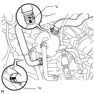
*a Yellow Paint Mark
-
Connect the 2 water by-pass hoses to the oil cooler.
Note
Make sure the pinching portion of each clip is facing the directions shown in the illustration and the paint marks are aligned as shown in the illustration.
-
-
ADD ENGINE COOLANT
-
ADD CONTINUOUSLY VARIABLE TRANSAXLE FLUID
-
INSPECT FOR COOLANT LEAK
-
INSTALL NO. 1 ENGINE UNDER COVER