CONTINUOUSLY VARIABLE TRANSAXLE SYSTEM Transmission Control Switch Circuit
DESCRIPTION
After moving the shift lever to M, it is possible to switch the shift range between "1" (M1 gear) and "7" (M7 gear) using the transmission control switch.
Moving the shift lever to "+" once raises the shift range by one, and moving the shift lever to "-" lowers the shift range by one.
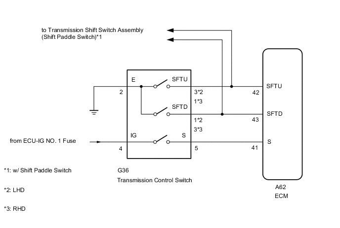
WIRING DIAGRAM
CAUTION / NOTICE / HINT
Note
-
Perform initialization when parts related to the continuously variable transaxle are replaced.
-
Check that no DTCs are stored after performing initialization.
-
Inspect the fuses for circuits related to this system before performing the following procedure.
PROCEDURE
-
CHECK HARNESS AND CONNECTOR (BATTERY - TRANSMISSION CONTROL SWITCH)
-
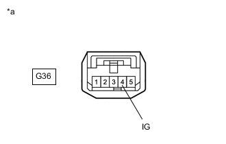
*a Front view of wire harness connector
(to Transmission Control Switch)
Disconnect the transmission control switch connector.
-
Measure the voltage according to the value(s) in the table below.
Standard Voltage Tester Connection Switch Condition Specified Condition G36-4 (IG) - Body ground Ignition switch ON 11 to 14 V G36-4 (IG) - Body ground Ignition switch off Below 1 V Result Proceed to OK NG
NG 
CHECK POWER SOURCE CIRCUIT
OK 
-
-
CHECK HARNESS AND CONNECTOR (TRANSMISSION CONTROL SWITCH - BODY GROUND)
-
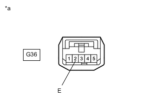
*a Front view of wire harness connector
(to Transmission Control Switch)
Disconnect the transmission control switch connector.
-
Measure the resistance according to the value(s) in the table below.
Standard Resistance Tester Connection Condition Specified Condition G36-2 (E) - Body ground Always Below 1 Ω Result Proceed to OK NG
NG
REPAIR OR REPLACE HARNESS OR CONNECTOR
OK
-
-
INSPECT TRANSMISSION CONTROL SWITCH (TRANSMISSION FLOOR SHIFT ASSEMBLY)
-
Disconnect the transmission control switch connector.
-
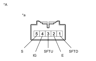
*A for LHD *a Component without harness connected
(Transmission Control Switch)
for LHD:
Measure the resistance according to the value(s) in the table below.
Standard Resistance Tester Connection Condition Specified Condition 4 (IG) - 5 (S) Shift lever in M, "+" or "-" Below 1 Ω 3 (SFTU) - 2 (E) Shift lever held in "+" (Up-shift) Below 1 Ω 1 (SFTD) - 2 (E) Shift lever held in "-" (Down-shift) Below 1 Ω 4 (IG) - 5 (S) Shift lever not in M, "+" or "-" 10 kΩ or higher 3 (SFTU) - 2 (E) Shift lever in M 10 kΩ or higher 1 (SFTD) - 2 (E) Shift lever in M 10 kΩ or higher -
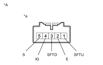
*A for RHD *a Component without harness connected
(Transmission Control Switch)
for RHD:
Measure the resistance according to the value(s) in the table below.
Standard Resistance Tester Connection Condition Specified Condition 4 (IG) - 5 (S) Shift lever in M, "+" or "-" Below 1 Ω 1 (SFTU) - 2 (E) Shift lever held in "+" (Up-shift) Below 1 Ω 3 (SFTD) - 2 (E) Shift lever held in "-" (Down-shift) Below 1 Ω 4 (IG) - 5 (S) Shift lever not in M, "+" or "-" 10 kΩ or higher 1 (SFTU) - 2 (E) Shift lever in M 10 kΩ or higher 3 (SFTD) - 2 (E) Shift lever in M 10 kΩ or higher Result Proceed to OK NG
NG
REPLACE TRANSMISSION CONTROL SWITCH (TRANSMISSION FLOOR SHIFT ASSEMBLY) Click here
OK
-
-
CHECK HARNESS AND CONNECTOR (TRANSMISSION CONTROL SWITCH - ECM)
-
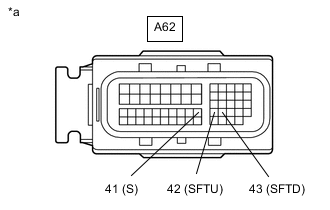
*a Front view of wire harness connector
(to ECM)
Disconnect the ECM connector.
-
Turn the ignition switch to ON.
-
Measure the voltage according to the value(s) in the table below.
Standard Voltage Tester Connection Condition Specified Condition A62-41 (S) - Body ground
-
Ignition switch ON
-
Shift lever in M, "+" or "-"
11 to 14 V A62-41 (S) - Body ground
-
Ignition switch ON
-
Shift lever not in M, "+" or "-"
Below 1 V -
-
Turn the ignition switch off.
-
Disconnect the spiral cable sub-assembly connector.
-
Measure the resistance according to the value(s) in the table below.
Standard Resistance Tester Connection Condition Specified Condition A62-42 (SFTU) - Body ground Shift lever held in "+" (Up-shift) Below 1 Ω A62-43 (SFTD) - Body ground Shift lever held in "-" (Down-shift) Below 1 Ω A62-42 (SFTU) - Body ground Shift lever in M 10 kΩ or higher A62-43 (SFTD) - Body ground Shift lever in M 10 kΩ or higher Result Proceed to OK NG
NG
REPAIR OR REPLACE HARNESS OR CONNECTOR
OK
-
-
REPLACE ECM
-
Replace the ECM.
-
for 3ZR-FAE:
-
for 3ZR-FE:
Result Proceed to NEXT -
NEXT
PERFORM INITIALIZATION Click here
-