OIL COOLER INSTALLATION
PROCEDURE
-
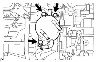
INSTALL OIL COOLER
-
Install the oil cooler to the continuously variable transaxle assembly with the 3 bolts.
- Torque:
- 13.5 N*m { 138 kgf*cm, 10 ft.*lbf }
-
Connect the 2 water by-pass hoses to the oil cooler, and slide the 2 clamps to secure it.
Note
Push on the 2 water by-pass hoses to the second rib on each oil cooler pipe.
-
-
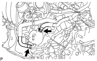
INSTALL OIL COOLER TUBE SUB-ASSEMBLY
*a White Paint Mark *b Yellow Paint Mark
-
Install the oil cooler tube sub-assembly with the 2 bolts.
- Torque:
- 5.5 N*m { 56 kgf*cm, 49 in.*lbf }
-
Connect the No. 3 oil cooler inlet hose and No. 3 oil cooler outlet hose to the oil cooler tube and radiator, and slide the 4 clamps to secure it.
Note
Make sure the pinching portion of each clip is facing the direction shown in the illustration and the paint marks are aligned as shown in the illustration.
-
-
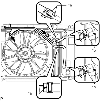
INSTALL TRANSMISSION OIL COOLER HOSE ASSEMBLY
*a White Paint Mark *b Yellow Paint Mark
-
Connect the 2 oil cooler inlet hoses and 2 oil cooler outlet hoses to the oil cooler inlet tube and oil cooler outlet tube, and slide the 4 clamps to secure it.
Note
Make sure the pinching portion of each clip is facing the direction shown in the illustration and the paint marks are aligned as shown in the illustration.
-
Connect the oil cooler inlet tube and oil cooler outlet tube to the transmission oil cooler hose assembly, and slide the 2 clamps to secure it.
Note
Make sure the pinching portion of each clip is facing the direction shown in the illustration and the paint marks are aligned as shown in the illustration.
-
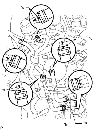
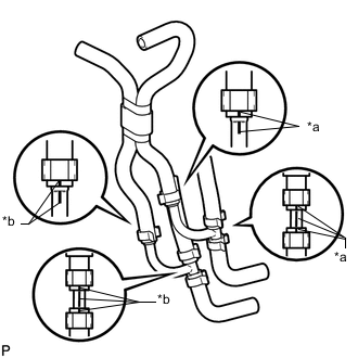
*a Yellow Paint Mark *b White Paint Mark *c Blue Paint Mark *d Green Paint Mark Connect the 2 transmission oil cooler hoses to the oil cooler tube, and slide the 2 clamps to secure it.
Note
Make sure the pinching portion of each clip is facing the direction shown in the illustration and the paint marks are aligned as shown in the illustration.
-
Connect the 2 oil cooler inlet hoses and 2 oil cooler outlet hoses to the transaxle and oil cooler, and slide the 4 clamps to secure it.
Note
Make sure the pinching portion of each clip is facing the direction shown in the illustration and the paint marks are aligned as shown in the illustration.
-
-
INSTALL BATTERY BRACKET REINFORCEMENT
-
INSTALL FRONT BATTERY BRACKET
-
CONNECT RADIATOR HOSE SUB-ASSEMBLY
-
INSTALL BATTERY TRAY
-
INSTALL BATTERY
-
INSTALL BATTERY CLAMP SUB-ASSEMBLY
-
CONNECT CABLE TO POSITIVE BATTERY TERMINAL
-
CONNECT CABLE TO NEGATIVE BATTERY TERMINAL
Note
When disconnecting the cable, some systems need to be initialized after the cable is reconnected Click here.
-
ADD ENGINE COOLANT
-
ADD CONTINUOUSLY VARIABLE TRANSAXLE FLUID
-
INSPECT FOR COOLANT LEAK
-
INSTALL REAR ENGINE UNDER COVER LH
-
INSTALL NO. 1 ENGINE UNDER COVER