CONTINUOUSLY VARIABLE TRANSAXLE SYSTEM, Diagnostic DTC:P1585
| DTC Code | DTC Name |
|---|---|
| P1585 | Acceleration Sensor Circuit |
DESCRIPTION
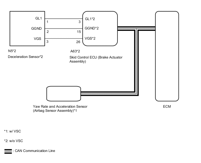
The ECM determines the vehicle inclination based on a signal from the yaw rate and acceleration sensor (airbag sensor assembly)*1 or deceleration sensor*2.
| DTC No. | Detection Item | DTC Detection Condition | Trouble Area | MIL | Memory |
|---|---|---|---|---|---|
| P1585 | Acceleration Sensor Circuit | 1. Diagnosis Condition 2. Malfunction Status 3. Malfunction Time 4. Other
|
|
- | DTC stored |
*1: w/ VSC
*2: w/o VSC
WIRING DIAGRAM
CAUTION / NOTICE / HINT
Note
-
Perform initialization when parts related to the continuously variable transaxle are replaced.
-
Check that no DTCs are stored after performing initialization.
Tech Tips
If a CAN communication DTC is output, perform troubleshooting for that DTC first.
PROCEDURE
-
CHECK DTC OUTPUT (CAN COMMUNICATION SYSTEM)
-
Check for DTCs of the CAN communication system.
-
for LHD:
-
for RHD:
Result Proceed to DTCs are not output DTCs are output -
DTCs are output 
GO TO CAN COMMUNICATION SYSTEM (DIAGNOSIS SYSTEM) for LHD: Click here for RHD: Click here
DTCs are not output 
-
-
READ VALUE USING GTS (G SENSOR)
-
Connect the GTS to the DLC3.
-
Turn the ignition switch to ON.
-
Turn the GTS on.
-
Enter the following menus: Powertrain / Engine and ECT / Data List.
Powertrain > Engine and ECT > Data ListTester Display G Sensor
Powertrain > Engine and ECT > Data ListTester Display Measurement Item Range Normal Condition Diagnostic Note G Sensor Converted output voltage of deceleration sensor min.: 0 V
max.: 79.998 V
Displays converted voltage of deceleration sensor
-
Vehicle on level ground: 2.31 V to 2.69 V
-
Decelerating: 1.88 V to 2.5 V
-
Accelerating: 2.5 V to 3.11 V
-
G sensor malfunction: Set to 1.87 V
-
Communication malfunction: Set to 1.87 V
- -
-
In accordance with the display on the GTS, read the Data List.
Result Result Proceed to Data displayed is as specified under Normal Condition (w/ VSC) A Data displayed is as specified under Normal Condition (w/o VSC) B Data displayed is not as specified under Normal Condition (w/ VSC) C Data displayed is not as specified under Normal Condition (w/o VSC) D
A
REPLACE SKID CONTROL ECU (BRAKE ACTUATOR ASSEMBLY) Click here
C 
REPLACE YAW RATE AND ACCELERATION SENSOR (AIRBAG SENSOR ASSEMBLY) Click here
D
CHECK HARNESS AND CONNECTOR (DECELERATION SENSOR - SKID CONTROL ECU) Click here
B
-
-
REPLACE SKID CONTROL ECU (BRAKE ACTUATOR ASSEMBLY)
-
Replace the skid control ECU (brake actuator assembly).
Result Proceed to NEXT
NEXT
PERFORM INITIALIZATION Click here
-
-
REPLACE YAW RATE AND ACCELERATION SENSOR (AIRBAG SENSOR ASSEMBLY)
-
Replace the yaw rate and acceleration sensor (airbag sensor assembly).
Result Proceed to NEXT
NEXT
PERFORM INITIALIZATION Click here
-
-
CHECK HARNESS AND CONNECTOR (DECELERATION SENSOR - SKID CONTROL ECU)
-
Disconnect the N5 deceleration sensor connector.
-
Disconnect the A63 skid control ECU (brake actuator assembly) connector.
-
Measure the resistance according to the value(s) in the table below.
Standard Resistance Tester Connection Condition Specified Condition N5-1 (GL1) - A63-3 (GL1) Always Below 1 Ω N5-2 (GGND) - A63-15 (GGND) Always Below 1 Ω N5-3 (VGS) - A63-26 (VGS) Always Below 1 Ω N5-1 (GL1) or A63-3 (GL1) - Body ground Always 10 kΩ or higher N5-2 (GGND) or A63-15 (GGND) - Body ground Always 10 kΩ or higher N5-3 (VGS) or A63-26 (VGS) - Body ground Always 10 kΩ or higher Result Proceed to OK NG
NG
REPAIR OR REPLACE HARNESS OR CONNECTOR
OK
-
-
INSPECT DECELERATION SENSOR (POWER SOURCE)
-
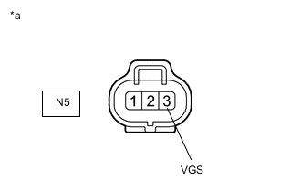
*a Front view of wire harness connector
(to Deceleration Sensor)
Disconnect the deceleration sensor connector.
-
Measure the voltage according to the value(s) in the table below.
Standard Voltage Tester Connection Switch Condition Specified Condition N5-3 (VGS) - Body ground Ignition switch ON 4.5 to 5.5 V Result Proceed to OK NG
NG
GO TO STEP 3 Click here
OK
-
-
INSPECT DECELERATION SENSOR (GL1 VOLTAGE)
-
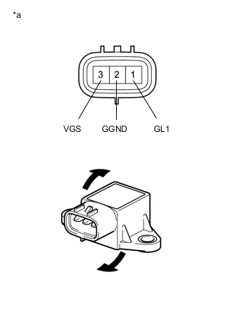
*a Component without harness connected
(Deceleration Sensor)
Remove the deceleration sensor.
-
Connect 3 dry cell batteries of 1.5 V in series.
-
Connect the positive (+) lead of the batteries to terminal 3 (VGS) and the negative (-) lead to terminal 2 (GGND) to apply a voltage of 4.5 V.
Note
-
Do not apply 6 V or higher to terminals 3 (VGS) and 2 (GGND).
-
If the sensor is dropped, replace it with a new one.
-
-
Measure the voltage according to the value(s) in the table below.
Standard Voltage Tester Connection Condition Specified Condition 1 (GL1) - 2 (GGND)
-
4.5 V applied to terminals 3 (VGS) and 2 (GGND)
-
Sensor not tilted
Approx. 2.5 V 1 (GL1) - 2 (GGND)
-
4.5 V applied to terminals 3 (VGS) and 2 (GGND)
-
Sensor tilted back and forth
Changes between approx. 0.5 V and 4.5 V Tech Tips
If the sensor is tilted too much, it may output the wrong value.
Result Proceed to OK NG -
OK
GO TO STEP 3 Click here
NG
-
-
REPLACE DECELERATION SENSOR
-
Replace the deceleration sensor.
Result Proceed to NEXT
NEXT
PERFORM INITIALIZATION Click here
-