VEHICLE STABILITY CONTROL SYSTEM TEST MODE PROCEDURE
 |
09843-18040 | Diagnosis Check Wire No. 2 |
-
WARNING LIGHT AND INDICATOR LIGHT INITIAL CHECK
-
Release the parking brake.
Note
When releasing the parking brake, move the shift lever to P (except Manual Transaxle) or set chocks (for Manual Transaxle) to prevent the vehicle from rolling.
Tech Tips
When the parking brake is applied or the brake fluid level is low, the brake warning light comes on.
-
When the ignition switch is turned to ON, check that the ABS warning, brake warning, VSC OFF indicator, TRC/TRAC OFF indicator*1, AUTO LSD indicator*2, downhill assist control indicator*3 and slip indicator lights come on for approximately 3 seconds.
-
*1: for Segment Display Type
-
*2: for 2WD
-
*3: w/ Downhill Assist Control
Tech Tips
-
If the skid control ECU (brake actuator assembly) stores any DTCs, the ABS warning and slip indicator lights will come on.
-
If any of the indicators remain on or do not come on, proceed to troubleshooting for the light circuits listed below.
Trouble Area See Procedure ABS warning light circuit (Remains on) ABS warning light circuit (Does not come on) Brake warning light circuit (Remains on) Brake warning light circuit (Does not come on) TRC/TRAC OFF indicator light circuit (Remains on) TRC/TRAC OFF indicator light circuit (Does not come on) VSC OFF indicator light circuit (Remains on) VSC OFF indicator light circuit (Does not come on) Slip indicator light circuit (Remains on) Slip indicator light circuit (Does not come on) Downhill assist control indicator light circuit (Remains on) Downhill assist control indicator light circuit (Does not come on) AUTO LSD indicator light circuit (Remains on) AUTO LSD indicator light circuit (Does not come on) -
-
-
SENSOR CHECK USING TEST MODE (SIGNAL CHECK) (When Using GTS)
Note
After replacement of the brake actuator assembly and/or yaw rate and acceleration sensor (airbag sensor assembly), perform zero point calibration of the yaw rate and acceleration sensor.
Tech Tips
-
If the ignition switch is turned from ON to ACC or off during Test Mode (signal check), DTCs recorded during the sensor check will be cleared.
-
During Test Mode (signal check), the skid control ECU (brake actuator assembly) records all DTCs detected in the sensor check. By performing Test Mode (signal check), the codes are cleared if a normal condition is confirmed. The remaining codes are the codes indicating where an abnormality was found.
-
Procedure to enter Test Mode.
-
Turn the ignition switch off.
-
Check that the steering wheel is in the straight-ahead position.
-
for Manual Transaxle:
Check that the shift lever is in neutral and apply the parking brake.
-
except Manual Transaxle:
Check that the shift lever is in P and apply the parking brake.
-
Connect the GTS to the DLC3.
-
Turn the ignition switch to ON.
-
Turn the GTS on.
-
Switch the skid control ECU (brake actuator assembly) to Test Mode using the GTS.
Enter the following menus: Chassis / ABS/VSC/TRC / Utility / Signal Check.
Chassis > ABS/VSC/TRC > UtilityTester Display Signal Check -
Check that the ABS warning and slip indicator lights come on for several seconds and then blink in the Test Mode blinking pattern (0.125 seconds on and 0.125 seconds off).
Tech Tips
If the ABS warning and slip indicator lights do not blink, inspect the TS and CG terminal circuit and ABS warning and slip indicator light circuits.
Trouble Area See Procedure TS and CG terminal circuit ABS warning light circuit (Remains on) ABS warning light circuit (Does not come on) Slip indicator light circuit (Remains on) Slip indicator light circuit (Does not come on)
-
-
-
ACCELERATION SENSOR CHECK (When Using GTS)
-
Keep the vehicle stationary on a level surface for 1 second or more.
Tech Tips
The acceleration sensor check can be performed with the master cylinder pressure sensor check below.
-
-
MASTER CYLINDER PRESSURE SENSOR CHECK (When Using GTS)
-
Leave the vehicle in a stationary condition and release the brake pedal for 1 second or more, and quickly and continuously depress the brake pedal with a force of 98 N (10 kgf, 22 lbf) or more for 1 second.
-
Check that the ABS warning light stays on for 3 seconds.
Tech Tips
-
Ensure that the ABS warning light comes on.
-
While the ABS warning light stays on, continue to depress the brake pedal with a force of 98 N (10 kgf, 22 lbf) or more.
-
The ABS warning light comes on for 3 seconds every time the brake pedal operation above is performed.
-
If the master cylinder pressure sensor check is not completed, depressing the brake pedal causes further decreases in vacuum in the brake booster, making the sensor check difficult to complete.
-
If the vacuum is insufficient, the master cylinder pressure sensor check may not be completed. In this case, run the engine at idle to obtain sufficient vacuum.
-
If the brake pedal is strongly depressed when the vacuum is insufficient, the brake warning light may come on in accordance with booster pressure control. In this case, run the engine at idle to obtain sufficient vacuum.
-
-
-
SPEED SENSOR CHECK (When Using GTS)
-
Check the speed sensor signal.
Note
Before performing the speed sensor signal check, complete the acceleration sensor and master cylinder pressure sensor checks.
-
Drive the vehicle straight ahead.
Accelerate the vehicle to a speed of 45 km/h (28 mph) or more for several seconds and check that the ABS warning light goes off.
-
The sensor check may not be completed if wheelspin occurs.
-
The ABS warning light blinks when the sensor check has been completed and the brake pedal is depressed.
-
The ABS warning light comes on immediately after a malfunction has been detected during the speed sensor check.
-
-
-
Stop the vehicle.
Note
-
The speed sensor check may not be completed if the sensor check is started with the steering wheel turned or one or more wheels spinning.
-
After the ABS warning light goes off and if the vehicle speed exceeds 80 km/h (50 mph), a sensor check code will be stored again. Decelerate or stop the vehicle before the speed reaches 80 km/h (50 mph).
-
If the sensor check has not been completed, the ABS warning light blinks during driving and the ABS system does not operate.
Tech Tips
When the sensor check has been completed, the ABS warning light remains off during driving and blinks in the Test Mode pattern while the vehicle is stationary.
-
-
-
TRACTION CONTROL SWITCH CHECK (When Using GTS)
-
for 4WD/AWD for Dot Display Type:
-
Check that the TRC OFF indicator on the multi-information display turns off when the VSC OFF switch (traction control switch) is pressed briefly.
-
-
for 4WD/AWD for Segment Display Type:
-
Check that the TRC/TRAC OFF indicator light turns off when the VSC OFF switch (traction control switch) is pressed briefly.
-
-
for 2WD:
-
Check that the AUTO LSD indicator light turns on when the VSC OFF switch (traction control switch) is pressed briefly.
-
-
Briefly press the VSC OFF switch (traction control switch) again.
-
-
DOWNHILL ASSIST CONTROL SWITCH CHECK (w/ Downhill Assist Control) (When Using GTS)
-
Turn the downhill assist control switch on.
-
Check that the downhill assist control indicator light blinks.
-
Turn the downhill assist control switch off.
-
Check that the downhill assist control indicator light turns off.
-
-
END OF SENSOR CHECK (When Using GTS)
-
If the sensor check is completed, the ABS warning light and slip indicator light blink (Test Mode) when the vehicle stops and the ABS warning light is off while the vehicle is being driven.
Note
-
When the yaw rate sensor, acceleration sensor, speed sensor, and master cylinder pressure sensor checks are completed, the sensor check is completed.
-
If the sensor check is not completed, the ABS warning light blinks even while the vehicle is being driven and the ABS does not operate.
-
-
-
READ DTC OF SIGNAL CHECK FUNCTION (When Using GTS)
-
Read the DTC(s) by following the GTS screen.
Note
-
If only the DTCs are displayed, repair the malfunction area and clear the DTCs.
-
If Test Mode sensor check DTCs and other DTCs are displayed or if only Test Mode sensor check DTCs are displayed, repair the malfunctions, clear the DTCs, and perform the Test Mode inspection again.
-
-
List of DTCs.
ABS Sensor DTC Code Detection Item Trouble Area C1271 Low Output Signal of Front Speed Sensor RH
-
Front speed sensor RH
-
Sensor installation
-
Speed sensor rotor
C1272 Low Output Signal of Front Speed Sensor LH
-
Front speed sensor LH
-
Sensor installation
-
Speed sensor rotor
C1273 Low Output Signal of Rear Speed Sensor RH
-
Rear speed sensor RH
-
Sensor installation
-
Speed sensor rotor
C1274 Low Output Signal of Rear Speed Sensor LH
-
Rear speed sensor LH
-
Sensor installation
-
Speed sensor rotor
C1275 Abnormal Change in Output Signal of Front Speed Sensor RH Speed sensor rotor C1276 Abnormal Change in Output Signal of Front Speed Sensor LH Speed sensor rotor C1277 Abnormal Change in Output Signal of Rear Speed Sensor RH Speed sensor rotor C1278 Abnormal Change in Output Signal of Rear Speed Sensor LH Speed sensor rotor C1279 Acceleration Sensor Output Voltage Malfunction
-
Acceleration sensor (airbag sensor assembly)
-
Sensor installation
C1281 Master Cylinder Pressure Sensor Output Malfunction
-
Stop light switch assembly
-
Master cylinder pressure sensor
VSC Sensor DTC Code Detection Item Trouble Area C1379* Downhill Assist Control Switch Malfunction Downhill assist control switch
-
*: w/ Downhill Assist Control
Tech Tips
The codes in this table are output only in Test Mode (signal check).
-
-
Turn the ignition switch off and disconnect the GTS.
-
-
SENSOR CHECK USING TEST MODE (SIGNAL CHECK) (When Using SST Check Wire)
Note
After replacement of the brake actuator assembly and/or yaw rate and acceleration sensor (airbag sensor assembly), perform zero point calibration of the yaw rate and acceleration sensor.
Tech Tips
-
If the ignition switch is turned from ON to ACC or off during Test Mode (signal check), DTCs recorded during the sensor check will be cleared.
-
During Test Mode (signal check), the skid control ECU (brake actuator assembly) records all DTCs detected in the sensor check. By performing Test Mode (signal check), the codes are cleared if a normal condition is confirmed. The remaining codes are the codes indicating where an abnormality was found.
-
Procedure to enter Test Mode.
-
Turn the ignition switch off.
-
Check that the steering wheel is in the straight-ahead position.
-
for Manual Transaxle:
Check that the shift lever is in neutral and apply the parking brake.
-
except Manual Transaxle:
Check that the shift lever is in P and apply the parking brake.
-
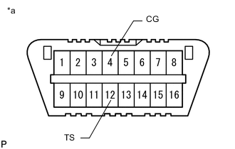
*a Front view of DLC3 Using SST, connect terminals 12 (TS) and 4 (CG) of the DLC3.
- SST
- 09843-18040
-
Turn the ignition switch to ON.
-
Check that the ABS warning and slip indicator lights come on for several seconds and then blink in Test Mode.
Tech Tips
If the ABS warning and slip indicator lights do not blink, inspect the TS and CG terminal circuit and ABS warning and slip indicator light circuits.
Trouble Area See Procedure TS and CG terminal circuit ABS warning light circuit (Remains on) ABS warning light circuit (Does not come on) Slip indicator light circuit (Remains on) Slip indicator light circuit (Does not come on)
-
-
-
ACCELERATION SENSOR CHECK (When Using SST Check Wire)
-
Keep the vehicle stationary on a level surface for 1 second or more.
Tech Tips
The acceleration sensor check can be performed with the master cylinder pressure sensor check below.
-
-
MASTER CYLINDER PRESSURE SENSOR CHECK (When Using SST Check Wire)
-
Leave the vehicle in a stationary condition and release the brake pedal for 1 second or more, and quickly and continuously depress the brake pedal with a force of 98 N (10 kgf, 22 lbf) or more for 1 second.
-
Check that the ABS warning light stays on for 3 seconds.
Tech Tips
-
Ensure that the ABS warning light comes on.
-
While the ABS warning light stays on, continue to depress the brake pedal with a force of 98 N (10 kgf, 22 lbf) or more.
-
The ABS warning light comes on for 3 seconds every time the brake pedal operation above is performed.
-
If the master cylinder pressure sensor check is not completed, depressing the brake pedal causes further decreases in vacuum in the brake booster, making the sensor check difficult to complete.
-
If the vacuum is insufficient, the master cylinder pressure sensor check may not be completed. In this case, run the engine at idle to obtain sufficient vacuum.
-
If the brake pedal is strongly depressed when the vacuum is insufficient, the brake warning light may come on in accordance with booster pressure control. In this case, run the engine at idle to obtain sufficient vacuum.
-
-
-
SPEED SENSOR CHECK (When Using SST Check Wire)
-
Check the speed sensor signal.
Note
Before performing the speed sensor signal check, complete the acceleration sensor and master cylinder pressure sensor signal checks.
-
Drive the vehicle straight ahead.
Accelerate the vehicle to a speed of 45 km/h (28 mph) or more for several seconds and check that the ABS warning light goes off.
-
The sensor check may not be completed if wheelspin occurs.
-
The ABS warning light blinks when the sensor check has been completed and the brake pedal is depressed.
-
The ABS warning light comes on immediately after a malfunction has been detected during the speed sensor check.
-
-
-
Stop the vehicle.
Note
-
The speed sensor check may not be completed if the sensor check is started with the steering wheel turned or one or more wheels spinning.
-
After the ABS warning light goes off and if the vehicle speed exceeds 80 km/h (50 mph), a sensor check code will be stored again. Decelerate or stop the vehicle before the speed reaches 80 km/h (50 mph).
-
If the sensor check has not been completed, the ABS warning light blinks during driving and the ABS system does not operate.
Tech Tips
When the sensor check has been completed, the ABS warning light remains on during driving and blinks in the Test Mode pattern while the vehicle is stationary.
-
-
-
TRACTION CONTROL SWITCH CHECK (When Using SST Check Wire)
-
for 4WD/AWD for Dot Display Type:
-
Check that the TRC OFF indicator on the multi-information display turns off when the VSC OFF switch (traction control switch) is pressed briefly.
-
-
for 4WD/AWD for Segment Display Type:
-
Check that the TRC/TRAC OFF indicator light turns off when the VSC OFF switch (traction control switch) is pressed briefly.
-
-
for 2WD:
-
Check that the AUTO LSD indicator light turns on when the VSC OFF switch (traction control switch) is pressed briefly.
-
-
Briefly press the VSC OFF switch (traction control switch) again.
-
-
DOWNHILL ASSIST CONTROL SWITCH CHECK (w/ Downhill Assist Control) (When Using SST Check Wire)
-
Turn the downhill assist control switch on.
-
Check that the downhill assist control indicator light blinks.
-
Turn the downhill assist control switch off.
-
Check that the downhill assist control indicator light turns off.
-
-
END OF SENSOR CHECK (When Using SST Check Wire)
-
If the sensor check is completed, the ABS warning light and slip indicator light blink (Test Mode) when the vehicle stops and the ABS warning light is off while the vehicle is being driven.
Note
-
When the yaw rate sensor, acceleration sensor, speed sensor, and master cylinder pressure sensor checks are completed, the sensor check is completed.
-
If the sensor check is not completed, the ABS warning light will blink even while the vehicle is driven and the ABS will not operate.
-
-
-
READ DTC OF SIGNAL CHECK FUNCTION (When Using SST Check Wire)
-
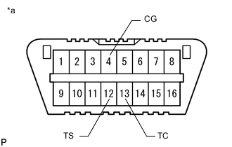
*a Front view of DLC3 Using SST, connect terminals 12 (TS), 13 (TC) and 4 (CG) of the DLC3.
- SST
- 09843-18040
-
Count the number of blinks of the ABS warning and slip indicator lights.
Note
-
If only DTCs other than Test Mode sensor check DTCs are displayed, repair the malfunctions and clear the DTCs.
-
If Test Mode sensor check DTCs and other DTCs are displayed or if only Test Mode sensor check DTCs are displayed, repair the malfunctions, clear the DTCs, and perform the Test Mode inspection again.
Tech Tips
-
When the system is operating correctly, each light will blink continuously in a pattern of 0.25 seconds on, and then 0.25 seconds off.
-
When one DTC is output, each light will output the same code at 4 second intervals (for example, code 21 would be output as 2 flashes, a 1.5 second pause, and then 1 flash).
-
When 2 or more DTCs are output, each light will output a different code at 2.5 second intervals, and when all codes have been output, there will be a 4 second pause and the sequence will repeat.
-
When multiple codes are stored, they are output in order starting with the lowest DTC number.
-
-
After performing the check, disconnect SST from terminals TS and CG, and TC and CG of the DLC3 and turn the ignition switch off.
-
Turn the ignition switch to ON.
Tech Tips
-
If the ignition switch is not turned to ON after SST is removed from the DLC3, the previous Test Mode will continue.
-
If the ignition switch is turned to ON with terminals TS and CG connected, the previous Test Mode will continue.
-
-
-
ABS Sensor DTC Code Detection Item Trouble Area 71 Low Output Signal of Front Speed Sensor RH
-
Front speed sensor RH
-
Sensor installation
-
Speed sensor rotor
72 Low Output Signal of Front Speed Sensor LH
-
Front speed sensor LH
-
Sensor installation
-
Speed sensor rotor
73 Low Output Signal of Rear Speed Sensor RH
-
Rear speed sensor RH
-
Sensor installation
-
Speed sensor rotor
74 Low Output Signal of Rear Speed Sensor LH
-
Rear speed sensor LH
-
Sensor installation
-
Speed sensor rotor
75 Abnormal Change in Output Signal of Front Speed Sensor RH Speed sensor rotor 76 Abnormal Change in Output Signal of Front Speed Sensor LH Speed sensor rotor 77 Abnormal Change in Output Signal of Rear Speed Sensor RH Speed sensor rotor 78 Abnormal Change in Output Signal of Rear Speed Sensor LH Speed sensor rotor 79 Acceleration Sensor Output Voltage Malfunction
-
Acceleration sensor (airbag sensor assembly)
-
Sensor installation
81 Master Cylinder Pressure Sensor Output Malfunction
-
Stop light switch assembly
-
Master cylinder pressure sensor
DTC OF TEST MODE (SIGNAL CHECK) FUNCTION (When Using SST Check Wire)
VSC Sensor DTC Code Detection Item Trouble Area 74* Downhill Assist Control Switch Malfunction Downhill assist control switch
-
*: w/ Downhill Assist Control
Tech Tips
The codes in this table are output only in Test Mode (signal check).
-