ANTI-LOCK BRAKE SYSTEM, Diagnostic DTC:C1273, C1274, C1403, C1404

| DTC Code | DTC Name |
|---|---|
| C1273 | Low Output Signal of Rear Speed Sensor RH (Test Mode DTC) |
| C1274 | Low Output Signal of Rear Speed Sensor LH (Test Mode DTC) |
| C1403 | Rear Speed Sensor RH Malfunction |
| C1404 | Rear Speed Sensor LH Malfunction |
DESCRIPTION
The speed sensor detects wheel speed and sends the appropriate signals to the skid control ECU (brake actuator assembly). These signals are used for ABS control.
Speed sensor rotors have rows of alternating N and S magnetic poles, and their magnetic fields change when the rotors turn.
Each speed sensor detects that magnetic change and sends a pulse signal to the skid control ECU (brake actuator assembly).
Tech Tips
When the connectors between the speed sensor and skid control ECU (brake actuator assembly) are connected, the following waveform is output.
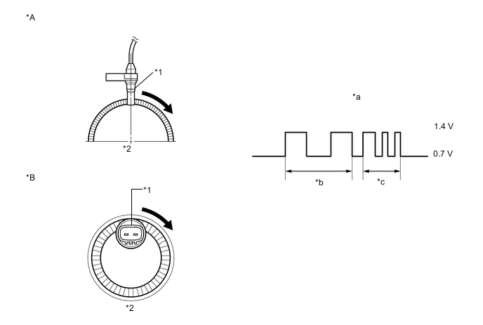
| *A | for 4WD/AWD | *B | for 2WD |
| *1 | Speed Sensor | *2 | Speed Sensor Rotor |
| *a | Waveform (Reference): Between Speed Sensor (-) and Body Ground |
*b | Low speed |
| *c | High speed | - | - |
| DTC No. | Detection Item | DTC Detection Condition | Trouble Area |
|---|---|---|---|
| C1273 | Low Output Signal of Rear Speed Sensor RH (Test Mode DTC) | Detected only during Test Mode. |
|
| C1274 | Low Output Signal of Rear Speed Sensor LH (Test Mode DTC) | Detected only during Test Mode. |
|
| C1403 | Rear Speed Sensor RH Malfunction | Any of the following is detected:
|
|
| C1404 | Rear Speed Sensor LH Malfunction | Any of the following is detected:
|
|
Tech Tips
-
DTC C1403 and C1273 are for the rear speed sensor RH.
-
DTC C1404 and C1274 are for the rear speed sensor LH.
WIRING DIAGRAM
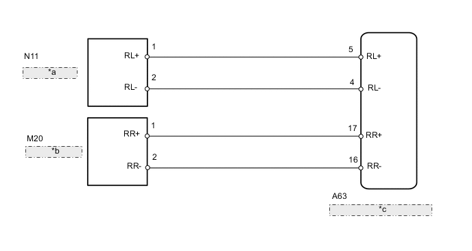
| *a | Rear Speed Sensor LH |
| *b | Rear Speed Sensor RH |
| *c | Skid Control ECU (Brake Actuator Assembly) |
CAUTION / NOTICE / HINT
Note
Disassembly of the speed sensor from the rear axle hub and bearing assembly is prohibited (for 2WD).
PROCEDURE
-
CHECK REAR SPEED SENSOR INSTALLATION
-
Turn the ignition switch off.
-
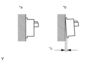
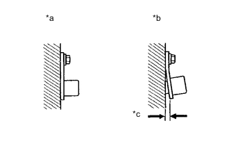
*a Normal *b Abnormal *c Clearance for 2WD:
Check the speed sensor installation.
OK There is no clearance between the sensor and the rear axle hub. Tech Tips
Because the rear axle hub and bearing assembly cannot be disassembled, if the rear speed sensor needs replacement, replace the rear axle hub and bearing assembly.
-
*a Normal *b Abnormal *c Clearance for 4WD/AWD:
Check the rear speed sensor installation.
OK There is no clearance between the sensor and the rear axle carrier. The installation bolt is tightened properly. Result Proceed to OK (for 2WD) OK (for 4WD/AWD) NG (for 2WD) NG (for 4WD/AWD)
OK (for 2WD) 
GO TO STEP 4 Click here
NG (for 2WD) 
REPLACE REAR AXLE HUB AND BEARING ASSEMBLY Click here
NG (for 4WD/AWD)
INSTALL REAR SPEED SENSOR CORRECTLY Click here
OK (for 4WD/AWD) 
-
-
INSPECT REAR SPEED SENSOR TIP
-
Remove the rear speed sensor.
-
Check the speed sensor tip.
OK No scratches, oil, or foreign matter on the sensor tip. Note
-
If no damage to the speed sensor tip is found during this inspection, do not replace the speed sensor.
-
If there is iron powder sticking to the rotor, this will result in a malfunction, so confirm that the rotor is not contaminated with foreign material before replacing the sensor.
-
Check the speed sensor signal after cleaning or replacement.
Result Proceed to OK NG -
NG
CLEAN OR REPLACE REAR SPEED SENSOR
OK
-
-
INSPECT REAR SPEED SENSOR ROTOR
-
Remove the rear axle hub and bearing assembly.
-
Check the speed sensor rotor.
OK No scratches, oil, or foreign matter on the rotors. Tech Tips
-
The rear speed sensor rotor is incorporated into the rear axle hub and bearing assembly.
-
If the rear speed sensor rotor needs to be replaced, replace it together with the rear axle hub and bearing assembly.
-
-
Reinstall the rear speed sensor and rear axle hub and bearing assembly.
Click here for the rear speed sensor
Click here for the rear axle hub and bearing assembly
Result Proceed to OK NG
NG
CLEAN OR REPLACE REAR SPEED SENSOR ROTOR
OK
-
-
READ VALUE USING GTS (REAR SPEED SENSOR)
-
Connect the GTS to the DLC3.
-
Start the engine.
-
Turn the GTS on.
-
Enter the following menus: Chassis / ABS/VSC/TRC / Data List.
-
According to the display on the GTS, read the Data List.
Chassis > ABS/VSC/TRC > Data ListTester Display Measurement Item Range Normal Condition Diagnostic Note RR Wheel Speed Rear wheel speed sensor RH reading Min.: 0 km/h (0 mph), Max.: 326.4 km/h (202 mph) Vehicle stopped: 0 km/h (0 mph) When driving at constant speed: No large fluctuations RL Wheel Speed Rear wheel speed sensor RH reading Min.: 0 km/h (0 mph), Max.: 326.4 km/h (202 mph) Vehicle stopped: 0 km/h (0 mph) When driving at constant speed: No large fluctuations
Chassis > ABS/VSC/TRC > Data ListTester Display RR Wheel Speed RL Wheel Speed -
Check that there is no difference between the speed value output from the speed sensor displayed on the GTS and the speed value displayed on the speedometer when driving the vehicle.
Tech Tips
Factors that affect the indicated vehicle speed include tire size, tire inflation, and tire wear. The speed indicated on the speedometer has an allowable margin of error. This can be tested using a speedometer tester (calibrated chassis dynamometer). For details about testing and the margin of error, see the reference chart.
OK The speed value output from the speed sensor displayed on the GTS is the same as the actual vehicle speed measured using a speedometer tester (calibrated chassis dynamometer). Tech Tips
-
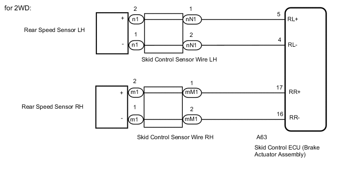
for 2WD:
The rear speed sensor and rear speed sensor rotor are incorporated into the rear axle hub and bearing assembly.
If the rear speed sensor rotor needs to be replaced, replace it together with the rear axle hub and bearing assembly with rear speed sensor.
-
If troubleshooting has been carried out according to the Problem Symptoms Table, refer back to the table and proceed to the next step.
Result Proceed to OK NG (for 2WD) NG (for 4WD/AWD) -
OK
USE SIMULATION METHOD TO CHECK Click here
NG (for 2WD)
REPLACE REAR AXLE HUB AND BEARING ASSEMBLY Click here
NG (for 4WD/AWD)
-
-
REPLACE REAR SPEED SENSOR
-
Turn the ignition switch off.
-
Replace the rear speed sensor.
Result Proceed to NEXT
NEXT
-
-
RECONFIRM DTC
-
Clear the DTCs.
Chassis > ABS/VSC/TRC > Clear DTCs -
Start the engine.
-
Drive the vehicle at a speed of 40 km/h (25 mph) or more for at least 60 seconds.
-
Check if the same DTC is recorded.
Chassis > ABS/VSC/TRC > Trouble CodesResult Proceed to DTCs C1403 and C1404 are not output DTCs C1403 and/or C1404 are output Tech Tips
-
The rear speed sensor rotor is incorporated into the rear axle hub and bearing assembly.
-
If the rear speed sensor rotor needs to be replaced, replace it together with the rear axle hub and bearing assembly.
-
If troubleshooting has been carried out according to the Problem Symptoms Table, refer back to the table and proceed to the next step.
-
DTCs C1403 and C1404 are not output
END
DTCs C1403 and/or C1404 are output
REPLACE REAR AXLE HUB AND BEARING ASSEMBLY Click here
-