ANTI-LOCK BRAKE SYSTEM TC and CG Terminal Circuit
DESCRIPTION
Connecting terminals TC and CG of the DLC3 causes the ECU to display the DTC by blinking the ABS warning light.
WIRING DIAGRAM
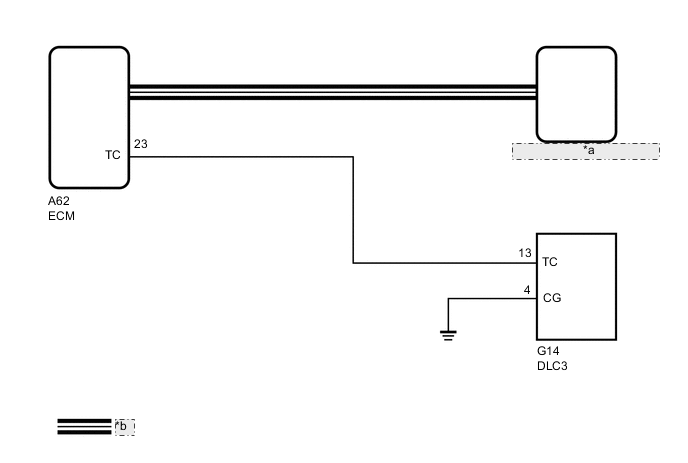
| *a | Skid Control ECU (Brake Actuator Assembly) |
| *b | CAN Communication Line |
CAUTION / NOTICE / HINT
Note
When replacing the skid control ECU (brake actuator assembly), perform acceleration sensor zero point calibration and CVT oil pressure calibration (for continuously variable transaxle).
K111: Click here
K111F: Click here
PROCEDURE
-
CHECK CAN COMMUNICATION SYSTEM
-
Check if CAN communication system DTCs are output.
Result Proceed to DTC is not output DTC is output
DTC is output 
CHECK CAN COMMUNICATION SYSTEM Click here
DTC is not output 
-
-
INSPECT DLC3
-
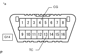
*a DLC3 Turn the ignition switch to ON.
-
Measure the voltage according to the value(s) in the table below.
Standard Voltage Tester Connection Switch Condition Specified Condition G14-13 (TC) - G14-4 (CG) Ignition switch ON 11 to 14 V Result Proceed to OK NG
OK 
GO TO STEP 5 Click here
NG
-
-
CHECK HARNESS AND CONNECTOR (TC of DLC3 - ECM)
-
Turn the ignition switch off.
-
Disconnect the A62 ECM connector.
-
Measure the resistance according to the value(s) in the table below.
Standard Resistance Tester Connection Condition Specified Condition G14-13 (TC) - A62-23 (TC) Always Below 1 Ω G14-13 (TC) - Body ground Always 10 kΩ or higher -
Reconnect the ECM connector.
Result Proceed to OK NG
NG
REPAIR OR REPLACE HARNESS OR CONNECTOR
OK
-
-
CHECK HARNESS AND CONNECTOR (CG of DLC3 - BODY GROUND)
-
Reconnect the A62 ECM connector.
-
Measure the resistance according to the value(s) in the table below.
Standard Resistance Tester Connection Condition Specified Condition G14-4 (CG) - Body ground Always Below 1 Ω Result Proceed to OK NG
NG
REPAIR OR REPLACE HARNESS OR CONNECTOR
OK
-
-
INSPECT ECM (TC of DLC3 INPUT)
-
*a DLC3 Turn the ignition switch off.
-
Using SST, connect terminals 13 (TC) and 4 (CG) of the DLC3.
- SST
- 09843-18040
-
Turn the ignition switch to ON.
-
Check that the malfunction indicator lamp is blinking.
Result Proceed to Malfunction indicator lamp is blinking (for 2AR-FE) Malfunction indicator lamp is blinking (for 3ZR-FE) Malfunction indicator lamp is not blinking
Malfunction indicator lamp is blinking (for 2AR-FE)
REPLACE ECM Click here
Malfunction indicator lamp is blinking (for 3ZR-FE)
REPLACE ECM Click here
Malfunction indicator lamp is not blinking
REPLACE BRAKE ACTUATOR ASSEMBLY Click here
-