ANTI-LOCK BRAKE SYSTEM TERMINALS OF ECU
 |
09843-18040 | Diagnosis Check Wire No. 2 |
-
TERMINALS OF ECU
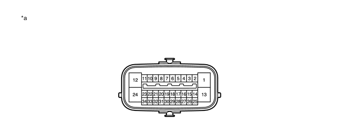
*a Component without harness connected
(Skid Control ECU [Brake Actuator Assembly])
- - Terminal No. (Symbol) Terminal Description 1 (GND1) Skid control ECU ground 2 - (Not used) 3 (GL1)* Deceleration sensor signal input 4 (RL-) Rear wheel speed LH (-) signal input 5 (RL+) Rear wheel speed LH (+) power supply output 6 (FR-) Front wheel speed RH (-) signal input 7 (FR+) Front wheel speed RH (+) power supply output 8 - (Not used) 9 - (Not used) 10 - (Not used) 11 - (Not used) 12 (+BS) Solenoid relay power supply 13 (GND2) Pump motor ground 14 (CANL) CAN communication line L 15 (GGND)* Deceleration sensor ground 16 (RR-) Rear wheel speed RH (-) signal input 17 (RR+) Rear wheel speed RH (+) power supply output 18 (FL-) Front wheel speed LH (-) signal input 19 (FL+) Front wheel speed LH (+) power supply output 20 - (Not used) 21 - (Not used) 22 (SP1) Speed signal output for speedometer 23 - (Not used) 24 (+BM) Motor relay power supply 25 (CANH) CAN communication line H 26 (VGS)* Deceleration sensor power supply 27 - (Not used) 28 (STP) Stop light switch input 29 - (Not used) 30 - (Not used) 31 - (Not used) 32 - (Not used) 33 - (Not used) 34 (IG1) ECU power supply
-
*: for 4WD/AWD
-
-
TERMINAL INSPECTION
-
Disconnect the A63 connector and measure the voltage or resistance on the wire harness side.
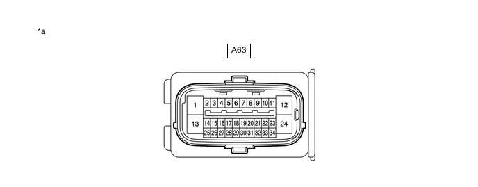
*a Front view of wire harness connector
(to Skid Control ECU [Brake Actuator Assembly])
- - Tech Tips
Voltage cannot be measured with the connector connected to the skid control (brake actuator assembly) as the connector is watertight.
Terminal No. (Symbol) Wiring Color Terminal Description Condition Specified Condition A63-1 (GND1) - Body ground W-B - Body ground Skid control ECU ground Always Below 1 Ω A63-12 (+BS) - Body ground W - Body ground Solenoid relay power supply Always 11 to 14 V A63-13 (GND2) - Body ground W-B - Body ground Pump motor ground Always Below 1 Ω A63-24 (+BM) - Body ground B - Body ground Motor relay power supply Always 11 to 14 V A63-25 (CANH) - A63-14 (CANL) R - W HIGH-level CAN bus wire - LOW-level CAN bus wire Cable disconnected from negative (-) battery terminal 54 to 69 Ω A63-28 (STP) - Body ground L - Body ground Stop light switch input Brake pedal depressed → released 8 to 14 V → Below 1.5 V A63-34 (IG1) - Body ground L - Body ground ECU power supply Ignition switch ON 11 to 14 V
-