LANE DEPARTURE ALERT SYSTEM Main Switch Circuit
DESCRIPTION
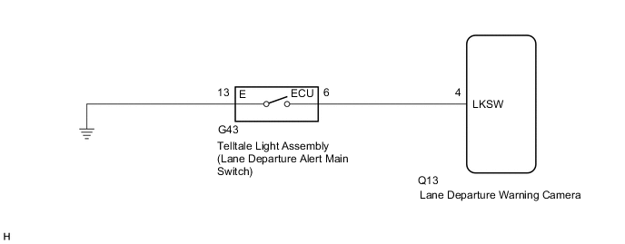
The lane departure warning camera receives a lane departure alert main switch signal from the telltale light assembly (lane departure alert main switch).
WIRING DIAGRAM
PROCEDURE
-
CHECK HARNESS AND CONNECTOR (TELLTALE LIGHT ASSEMBLY [LANE DEPARTURE ALERT MAIN SWITCH] - LANE DEPARTURE WARNING CAMERA AND BODY GROUND)
-
Disconnect the G43 telltale light assembly (lane departure alert main switch) connector.
-
Disconnect the Q13 lane departure warning camera connector.
-
Measure the resistance according to the value(s) in the table below.
Standard Resistance Tester Connection Condition Specified Condition G43-6 (ECU) - Q13-4 (LKSW) Always Below 1 Ω G43-6 (ECU) - Body ground Always 10 kΩ or higher G43-13 (E) - Body ground Always Below 1 Ω Result Proceed to OK NG
NG 
REPAIR OR REPLACE HARNESS OR CONNECTOR
OK 
-
-
INSPECT TELLTALE LIGHT ASSEMBLY
-
Remove the telltale light assembly.
-
Inspect the telltale light assembly.
Result Proceed to OK NG
OK
PROCEED TO NEXT SUSPECTED AREA SHOWN IN PROBLEM SYMPTOMS TABLE Click here
NG
REPLACE TELLTALE LIGHT ASSEMBLY Click here
-