LANE DEPARTURE ALERT SYSTEM TERMINALS OF ECU
-
CHECK LANE DEPARTURE WARNING CAMERA

Terminal No. (Symbol) Wiring Color Terminal Description Condition Specified Condition Q13-4 (LKSW) - Q13-11 (GND) B - W-B Lane departure alert main switch signal Ignition switch ON, lane departure alert main switch off 10 kΩ or higher Ignition switch ON, lane departure alert main switch on Below 1 Ω Q13-6 (CA1P) - Q13-11 (GND) B - W-B CAN communication signal Ignition switch ON Pulse generation
(Waveform 1)
Q13-7 (IGB) - Q13-11 (GND) GR - W-B Power source (IG) Ignition switch ON 11 to 14 V*1 Ignition switch ON 10.5 to 14 V*2 Ignition switch off Below 1 V Q13-8 (BZ) - Body ground R - Body ground Skid control buzzer assembly output Ignition switch ON, buzzer not sounding 11 to 14 V Ignition switch ON, buzzer sounding 0 to 1.5 V Q13-11 (GND) - Body ground W-B - Body ground Ground Always Below 1 Ω Q13-12 (CA1N) - Q13-11 (GND) W - W-B CAN communication signal Ignition switch ON Pulse generation
(Waveform 1)
-
*1: w/o Stop and Start System
-
*2: w/ Stop and Start System
Tech Tips
Oscilloscope waveform samples are provided here for informational purposes. Noise and fluttering waveforms have been omitted.
-
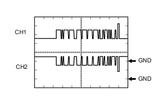
Waveform 1 (CAN communication signal)
Item Content Tester Connection CH1: Q13-6 (CA1P) - Q13-11 (GND)
CH2: Q13-12 (CA1N) - Q13-11 (GND)
Tool Setting 1 V/DIV., 50 μs./DIV. Condition Ignition switch ON Tech Tips
The waveform will vary depending on the content of the digital communication (digital signal).
-