SPEED LIMITER SYSTEM TERMINALS OF ECM
-
CHECK ECM (for 2WW)
Tech Tips
The standard voltage between each pair of the ECM terminals is shown in the table below. The appropriate conditions for checking each pair of the terminals are also indicated.
The result of checks should be compared with the standard voltage for that pair of terminals, and displayed in the "Specified Condition" column.
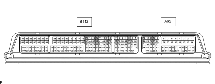
The illustration above can be used as a reference to identify the ECM terminal locations.
for 2WW: Terminal No. (Symbol) Wiring Color Terminal Description Condition Specified Condition A62-4 (E1) - Body ground W-B - Body ground Ground Always Below 1 Ω A62-15 (BATT) - A62-4 (E1) W - W-B Power source circuit Always 11 to 14 V A62-37 (IGSW) - A62-4 (E1) B - W-B IG power source circuit Ignition switch ON 11 to 14 V Ignition switch off Below 1 V A62-49 (ASLM) - A62-42 (ECCS) P - BR Speed limiter switch signal Speed limiter switch on Below 1 Ω Speed limiter switch off 10 kΩ or higher -
CHECK ECM (for 3ZR-FAE)
Tech Tips
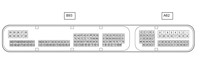
The standard normal voltage between each pair of the ECM terminals is shown in the table below. The appropriate conditions for checking each pair of the terminals are also indicated. The result of checks should be compared with the standard normal voltage for that pair of the terminals, which is displayed in the Specified Condition column. The illustration above can be used as a reference to identify the ECM terminal locations.
for 3ZR-FAE: Terminal No. (Symbol) Wiring Color Terminal Description Condition Specified Condition A62-1 (BATT) - B93-59 (E1) W - BR Power source circuit Always 11 to 14 V A62-6 (IGSW) - B93-59 (E1) B - BR Ignition switch signal Ignition switch ON 11 to 14 V A62-20 (ASLM) - A62-35 (ECCS) P - BR Speed limiter switch signal Speed limiter switch on Below 1 Ω Speed limiter switch off 10 kΩ or higher B93-59 (E1) - Body ground BR - Body ground Ground Always Below 1 Ω