CRUISE CONTROL SYSTEM TERMINALS OF ECM
-
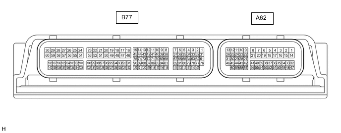
CHECK ECM (for 2AR-FE)
-
Disconnect the A62 and B77 ECM connectors.
-
Measure the resistance and voltage according to the value(s) in the table below.
Terminal No. (Symbol) Wiring Color Terminal Description Condition Specified Condition A62-11 (STP) - B77-16 (E1) L - BR Stop light signal Brake pedal depressed 7.5 to 14 V A62-11 (STP) - B77-16 (E1) L - BR Stop light signal Brake pedal released Below 1.5 V A62-40 (CCS) - B77-16 (E1) L - BR Cruise control switch circuit Cruise control switch off 1 MΩ or higher A62-40 (CCS) - B77-16 (E1) L - BR Cruise control switch circuit Cruise control switch on Below 2.5 Ω A62-40 (CCS) - B77-16 (E1) L - BR Cruise control switch circuit +RES switch on 235 to 245 Ω A62-40 (CCS) - B77-16 (E1) L - BR Cruise control switch circuit -SET switch on 617 to 643 Ω A62-40 (CCS) - B77-16 (E1) L - BR Cruise control switch circuit CANCEL switch on 1509 to 1571 Ω A62-24 (ST1-) - B77-16 (E1) GR - BR Stop light signal Ignition switch ON, brake pedal depressed Below 1.5 V A62-24 (ST1-) - B77-16 (E1) GR - BR Stop light signal Ignition switch ON, brake pedal released 7.5 to 14 V B77-67 (D) - B77-16 (E1)*1 B - BR D shift position signal Ignition switch ON, shift lever in D 11 to 14 V B77-67 (D) - B77-16 (E1)*1 B - BR D shift position signal Ignition switch ON, shift lever is not in D Below 1 V B77-67 (D) - B77-16 (E1)*2 L - BR Clutch switch signal Ignition switch ON, clutch pedal depressed 11 to 14 V B77-67 (D) - B77-16 (E1)*2 L - BR Clutch switch signal Ignition switch ON, clutch pedal released Below 1 V B77-66 (R) - B77-16 (E1)*1 R - BR R shift position signal Ignition switch ON, shift lever in R 11 to 14 V B77-66 (R) - B77-16 (E1)*1 R - BR R shift position signal Ignition switch ON, shift lever is not in R Below 1 V B77-70 (P) - B77-16 (E1)*1 L - BR P shift position signal Ignition switch ON, shift lever in P 11 to 14 V B77-70 (P) - B77-16 (E1)*1 L - BR P shift position signal Ignition switch ON, shift lever is not in P Below 1 V B77-71 (N) - B77-16 (E1)*1 Y - BR N shift position signal Ignition switch ON, shift lever in N 11 to 14 V B77-71 (N) - B77-16 (E1)*1 Y - BR N shift position signal Ignition switch ON, shift lever is not in N Below 1 V A62-1 (BATT) - Body ground W - Body ground Battery power supply Always 11 to 14 V B77-16 (E1) - Body ground BR - Body ground Ground Always Below 1 Ω A62-27 (S) - B77-16 (E1)*1 L - BR S shift position switch signal Ignition switch ON and shift lever in S 11 to 14 V A62-27 (S) - B77-16 (E1)*1 L - BR S shift position switch signal Ignition switch ON, shift lever is not in S Below 1 V A62-43 (SFTD) - B77-16 (E1)*1 Y - BR Downshift switch signal Ignition switch ON and shift lever in S 11 to 14 V Ignition switch ON and shift lever in "-" (downshift) Below 1 V A62-42 (SFTU) - B77-16 (E1)*1 LG - BR Upshift switch signal Ignition switch ON and shift lever in S 11 to 14 V Ignition switch ON and shift lever in "+" (upshift) Below 1 V *1: for Automatic Transaxle
*2: for Manual Transaxle
-
-
CHECK ECM (for 3ZR-FE (K111))
-
Disconnect the A62 and B75 ECM connectors.

-
Measure the resistance and voltage according to the value(s) in the table below.
Terminal No. (Symbol) Wiring Color Terminal Description Condition Specified Condition A62-9 (STP) - B75-16 (E1) L - BR Stop light signal Brake pedal depressed 7.5 to 14 V A62-9 (STP) - B75-16 (E1) L - BR Stop light signal Brake pedal released Below 1.5 V A62-60 (CCS) - B75-16 (E1) L - BR Cruise control switch circuit Cruise control switch off 1 MΩ or higher A62-60 (CCS) - B75-16 (E1) L - BR Cruise control switch circuit Cruise control switch on Below 2.5 Ω A62-60 (CCS) - B75-16 (E1) L - BR Cruise control switch circuit +RES switch on 235 to 245 Ω A62-60 (CCS) - B75-16 (E1) L - BR Cruise control switch circuit -SET switch on 617 to 643 Ω A62-60 (CCS) - B75-16 (E1) L - BR Cruise control switch circuit CANCEL switch on 1509 to 1571 Ω A62-10 (ST1-) - B75-16 (E1) GR - BR Stop light signal Ignition switch ON, brake pedal depressed Below 1.5 V A62-10 (ST1-) - B75-16 (E1) GR - BR Stop light signal Ignition switch ON, brake pedal released 7.5 to 14 V B75-81 (D) - B75-16 (E1) B - BR D shift position signal Ignition switch ON, shift lever in D 11 to 14 V B75-81 (D) - B75-16 (E1) B - BR D shift position signal Ignition switch ON, shift lever is not in D Below 1 V B75-79 (R) - B75-16 (E1) R - BR R shift position signal Ignition switch ON, shift lever in R 11 to 14 V B75-79 (R) - B75-16 (E1) R - BR R shift position signal Ignition switch ON, shift lever is not in R Below 1 V B75-97 (N) - B75-16 (E1) Y - BR N shift position signal Ignition switch ON, shift lever in N 11 to 14 V B75-97 (N) - B75-16 (E1) Y - BR N shift position signal Ignition switch ON, shift lever is not in N Below 1 V B75-99 (P) - B75-16 (E1) L - BR P shift position signal Ignition switch ON, shift lever in P 11 to 14 V B75-99 (P) - B75-16 (E1) L - BR P shift position signal Ignition switch ON, shift lever is not in P Below 1 V A62-1 (BATT) - Body ground W - Body ground Battery power supply Always 11 to 14 V B75-16 (E1) - Body ground BR - Body ground Ground Always Below 1 Ω A62-41 (S) - B75-16 (E1) L - BR M shift position switch signal Ignition switch ON, shift lever in M 11 to 14 V A62-41 (S) - B75-16 (E1) L - BR M shift position switch signal Ignintion switch ON, shift lever is not in M Below 1 V A62-43 (SFTD) - B75-16 (E1) Y - BR Downshift switch signal Ignition switch ON and shift lever in M 11 to 14 V A62-43 (SFTD) - B75-16 (E1) Y - BR Downshift switch signal Ignition switch ON and shift lever in "-" (downshift) Below 1 V A62-42 (SFTU) - B75-16 (E1) LG - BR Upshift switch signal Ignition switch ON and shift lever in M 11 to 14 V A62-42 (SFTU) - B75-16 (E1) LG - BR Upshift switch signal Ignition switch ON and shift lever in "+" (upshift) Below 1 V
-
-
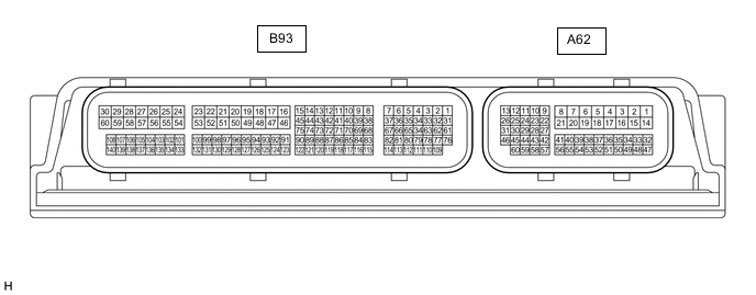
CHECK ECM (for 3ZR-FAE, 3ZR-FE (except K111))
-
Disconnect the A62 and B93 ECM connectors.
-
Measure the resistance and voltage according to the value(s) in the table below.
Terminal No. (Symbol) Wiring Color Terminal Description Condition Specified Condition A62-9 (STP) - B93-16 (E1) L - BR Stop light signal Brake pedal depressed 7.5 to 14 V A62-9 (STP) - B93-16 (E1) L - BR Stop light signal Brake pedal released Below 1.5 V A62-36 (CCS) - A62-35 (ECCS) L - BR Cruise control switch circuit Cruise control switch off 1 MΩ or higher A62-36 (CCS) - A62-35 (ECCS) L - BR Cruise control switch circuit Cruise control switch on Below 2.5 Ω A62-36 (CCS) - A62-35 (ECCS) L - BR Cruise control switch circuit +RES switch on 235 to 245 Ω A62-36 (CCS) - A62-35 (ECCS) L - BR Cruise control switch circuit -SET switch on 617 to 643 Ω A62-36 (CCS) - A62-35 (ECCS) L - BR Cruise control switch circuit CANCEL switch on 1509 to 1571 Ω A62-10 (ST1-) - B93-16 (E1) GR - BR Stop light signal Ignition switch ON, brake pedal depressed Below 1.5 V A62-10 (ST1-) - B93-16 (E1) GR - BR Stop light signal Ignition switch ON, brake pedal released 7.5 to 14 V B93-65 (D) - B93-16 (E1)*1 B - BR D shift position signal Ignition switch ON, shift lever in D 11 to 14 V B93-65 (D) - B93-16 (E1)*1 B - BR D shift position signal Ignition switch ON, shift lever is not in D Below 1 V B93-65 (D) - B93-16 (E1)*2 L - BR Clutch switch signal Ignition switch ON, clutch pedal depressed 11 to 14 V B93-65 (D) - B93-16 (E1)*2 L - BR Clutch switch signal Ignition switch ON, clutch pedal released Below 1 V B93-64 (R) - B93-16 (E1)*1 R - BR R shift position signal Ignition switch ON, shift lever in R 11 to 14 V B93-64 (R) - B93-16 (E1)*1 R - BR R shift position signal Ignition switch ON, shift lever is not in R Below 1 V B93-69 (N) - B93-16 (E1)*1 Y - BR N shift position signal Ignition switch ON, shift lever in N 11 to 14 V B93-69 (N) - B93-16 (E1)*1 Y - BR N shift position signal Ignition switch ON, shift lever is not in N Below 1 V B93-70 (P) - B93-16 (E1)*1 L - BR P shift position signal Ignition switch ON, shift lever in P 11 to 14 V B93-70 (P) - B93-16 (E1)*1 L - BR P shift position signal Ignition switch ON, shift lever is not in P Below 1 V A62-1 (BATT) - Body ground W - Body ground Battery power supply Always 11 to 14 V B93-16 (E1) - Body ground BR - Body ground Ground Always Below 1 Ω A62-41 (S) - B93-16 (E1)*1 L - BR M shift position switch signal Ignition switch ON, shift lever in M 11 to 14 V A62-41 (S) - B93-16 (E1)*1 L - BR M shift position switch signal Ignintion switch ON, shift lever is not in M Below 1 V A62-43 (SFTD) - B93-16 (E1)*1 Y - BR Downshift switch signal Ignition switch ON and shift lever in M 11 to 14 V A62-43 (SFTD) - B93-16 (E1)*1, *3 Y - BR Downshift switch signal Ignition switch ON and "-" shift paddle operated and held (downshift) Below 1 V A62-43 (SFTD) - B93-16 (E1)*1 Y - BR Downshift switch signal Ignition switch ON and shift lever in "-" (downshift) Below 1 V A62-42 (SFTU) - B93-16 (E1)*1 LG - BR Upshift switch signal Ignition switch ON and shift lever in M 11 to 14 V A62-42 (SFTU) - B93-16 (E1)*1, *3 LG - BR Upshift switch signal Ignition switch ON and "+" shift paddle operated and held (upshift) Below 1 V A62-42 (SFTU) - B93-16 (E1)*1 LG - BR Upshift switch signal Ignition switch ON and shift lever in "+" (upshift) Below 1 V *1: for CVT
*2: for Manual Transaxle
*3: w/ Shift Paddle Switch
-
-
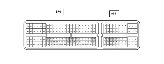
CHECK ECM (for 2AD-FHV, 2AD-FTV)
-
Disconnect the A61 and B76 ECM connectors.
-
Measure the resistance and voltage according tothe value(s) in the table below.
Terminal No. (Symbol) Wiring Color Terminal Description Condition Specified Condition A61-35 (STP) - B76-109 (E1) L - BR Stop light signal Brake pedal depressed 7.5 to 14 V A61-35 (STP) - B76-109 (E1) L - BR Stop light signal Brake pedal released 0 to 1.5 V A61-23 (CCS) - B76-109 (E1) L - BR Cruise control switch circuit Cruise control switch off 1 MΩ or higher A61-23 (CCS) - B76-109 (E1) L - BR Cruise control switch circuit Cruise control switch on Below 2.5 Ω A61-23 (CCS) - B76-109 (E1) L - BR Cruise control switch circuit +RES switch on 235 to 245 Ω A61-23 (CCS) - B76-109 (E1) L - BR Cruise control switch circuit -SET switch on 617 to 643 Ω A61-23 (CCS) - B76-109 (E1) L - BR Cruise control switch circuit CANCEL switch on 1509 to 1571 Ω A61-34 (ST1-) - B76-109 (E1) GR - BR Stop light signal Ignition switch ON, brake pedal depressed 0 to 1.5 V A61-34 (ST1-) - B76-109 (E1) GR - BR Stop light signal Ignition switch ON, brake pedal released 7.5 to 14 V B76-73 (D) - B76-109 (E1)*1 B - BR D shift position signal Ignition switch ON, shift lever in D 11 to 14 V B76-73 (D) - B76-109 (E1)*1 B - BR D shift position signal Ignition switch ON, shift lever is not in D Below 1 V B76-73 (D) - B76-109 (E1)*2 L - BR Clutch switch signal Ignition switch ON, clutch pedal depressed 11 to 14 V B76-73 (D) - B76-109 (E1)*2 L - BR Clutch switch signal Ignition switch ON, clutch pedal released Below 1 V B76-71 (R) - B76-109 (E1)*1 R - BR R shift position signal Ignition switch ON, shift lever in R 11 to 14 V B76-71 (R) - B76-109 (E1)*1 R - BR R shift position signal Ignition switch ON, shift lever is not in R Below 1 V B76-53 (P) - B76-109 (E1)*1 L - BR P shift position signal Ignition switch ON, shift lever in P 11 to 14 V B76-53 (P) - B76-109 (E1)*1 L - BR P shift position signal Ignition switch ON, shift lever is not in P Below 1 V B76-70 (N) - B76-109 (E1)*1 Y - BR N shift position signal Ignition switch ON, shift lever in N 11 to 14 V B76-70 (N) - B76-109 (E1)*1 Y - BR N shift position signal Ignition switch ON, shift lever is not in N Below 1 V A61-2 (BATT) - Body ground W - Body ground Battery power supply Always 11 to 14 V B76-109 (E1) - Body ground BR - Body ground Ground Always Below 1 Ω A61-9 (S) - B76-109 (E1)*1 L - BR M shift position switch signal Ignition switch ON, shift lever in M 11 to 14 V A61-9 (S) - B76-109 (E1)*1 L - BR M shift position switch signal Ignition switch ON, shift lever is not in M Below 1 V A61-28 (SFTD) - B76-109 (E1)*1 Y - BR Downshift switch signal Ignition switch ON and shift lever in M 11 to 14 V A61-28 (SFTD) - B76-109 (E1)*1 Y - BR Downshift switch signal Ignition switch ON and shift lever in "-" (downshift) Below 1 V B76-61 (SFTU) - B76-109 (E1)*1 LG - BR Upshift switch signal Ignition switch ON and shift lever in M 11 to 14 V B76-61 (SFTU) - B76-109 (E1)*1 LG - BR Upshift switch signal Ignition switch ON and shift lever in "+" (upshift) Below 1 V *1: for Automatic Transaxle
*2: for Manual Transaxle
-
-
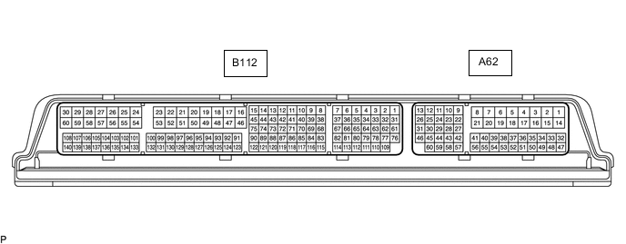
CHECK ECM (for 2WW)
-
Disconnect the A62 and B112 ECM connectors.
-
Measure the resistance and voltage according tothe value(s) in the table below.
Terminal No. (Symbol) Wiring Color Terminal Description Condition Specified Condition A62-48 (STP) - A62-4 (E1) L - W-B Stop light signal Brake pedal depressed 7.5 to 14 V A62-48 (STP) - A62-4 (E1) L - W-B Stop light signal Brake pedal released 0 to 1.5 V A62-41 (CCS) - A62-42 (ECCS) L - BR Cruise control switch circuit Cruise control switch off 1 MΩ or higher A62-41 (CCS) - A62-42 (ECCS) L - BR Cruise control switch circuit Cruise control switch on Below 2.5 Ω A62-41 (CCS) - A62-42 (ECCS) L - BR Cruise control switch circuit +RES switch on 235 to 245 Ω A62-41 (CCS) - A62-42 (ECCS) L - BR Cruise control switch circuit -SET switch on 617 to 643 Ω A62-41 (CCS) - A62-42 (ECCS) L - BR Cruise control switch circuit CANCEL switch on 1509 to 1571 Ω A62-10 (ST1-) - A62-4 (E1) GR - W-B Stop light signal Ignition switch ON, brake pedal depressed 0 to 1.5 V A62-10 (ST1-) - A62-4 (E1) GR - W-B Stop light signal Ignition switch ON, brake pedal released 7.5 to 14 V A62-7 (D) - A62-4 (E1) L - W-B Clutch switch signal Ignition switch ON, clutch pedal depressed 11 to 14 V A62-7 (D) - A62-4 (E1) L - W-B Clutch switch signal Ignition switch ON, clutch pedal released Below 1 V A62-15 (BATT) - Body ground W - Body ground Battery power supply Always 11 to 14 V A62-4 (E1) - Body ground W-B - Body ground Ground Always Below 1 Ω
-