AIR COOLED OIL COOLER INSTALLATION
PROCEDURE
-
INSTALL OIL COOLER ASSEMBLY
-
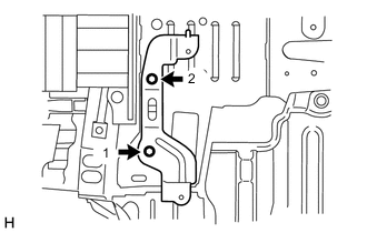
Install the No. 1 oil cooler bracket with the 2 bolts. Tighten the bolts in the order shown in the illustration.
- Torque:
- 5.5 N*m { 56 kgf*cm, 49 in.*lbf }
-
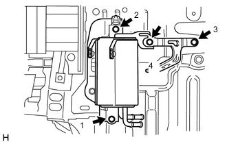
Install the oil cooler assembly and No. 2 oil cooler bracket with the 4 bolts. Tighten the bolts in the order shown in the illustration.
- Torque:
- 5.5 N*m { 56 kgf*cm, 49 in.*lbf }
-
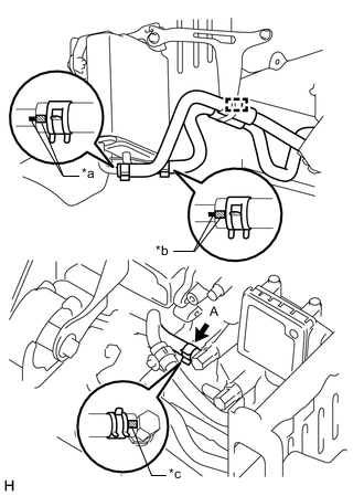
*a Yellow Paint Mark *b White Paint Mark *c Pink Paint Mark Connect the hose clamp and install the oil cooler hose assembly, and slide the clips to secure it.
Note
-
Make sure the paint marks are aligned as shown in the illustration.
-
Make sure that the claws marked A in the illustration are facing toward the front end of the vehicle.
-
Position the claws of the clips so that they do not interfere with other parts unless otherwise specified.
-
-
-
INSTALL TRANSMISSION OIL COOLER AIR DUCT
-
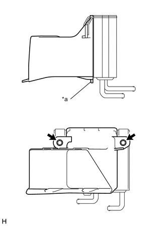
*a Rib Attach the rib of the transmission oil cooler air duct, and then temporarily install the oil cooler assembly with the 2 bolts.
-
Tighten the 2 bolts.
- Torque:
- 5.5 N*m { 56 kgf*cm, 49 in.*lbf }
-
-
INSTALL OIL COOLER TUBE SUB-ASSEMBLY
-
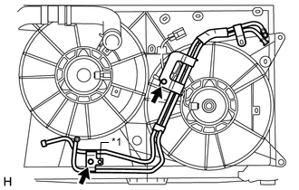
*1 Pin Install the oil cooler tube sub-assembly with the 2 bolts. Tighten the bolts in the order shown in the illustration.
- Torque:
- 5.5 N*m { 56 kgf*cm, 49 in.*lbf }
Note
Insert the pin of the radiator fan shroud into the hole of the oil cooler tube sub-assembly.
-
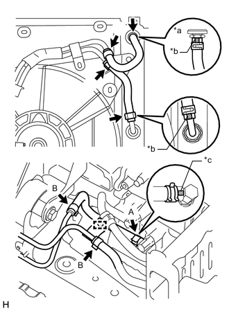
*a Upper View *b Yellow Paint Mark *c Green Paint Mark Install the No. 1 oil cooler inlet hose, No. 2 oil cooler inlet hose and No. 2 oil cooler outlet hose, and slide the clips to secure it.
Note
-
Make sure that the paint marks are in the position shown in the illustration.
-
Make sure that the claws marked A in the illustration are facing toward the front end of the vehicle, and that the claws marked B in the illustration are facing toward the underside of the vehicle.
-
Position the claws of the clips so that they do not interfere with other parts unless otherwise specified.
-
-
-
ADD AUTOMATIC TRANSAXLE FLUID
-
ADJUST AUTOMATIC TRANSAXLE FLUID
-
INSTALL FRONT BUMPER COVER
-
INSTALL REAR ENGINE UNDER COVER LH
-
INSTALL NO. 1 ENGINE UNDER COVER