PARK / NEUTRAL POSITION SWITCH INSTALLATION
PROCEDURE
-
INSTALL PARK/NEUTRAL POSITION SWITCH ASSEMBLY
-
Install the park/neutral position switch assembly to the control shaft.
-
Temporarily install the 2 bolts.
Tech Tips
The bolts will be tightened to a torque specification during the park/neutral position switch assembly adjustment procedure.
-
Temporarily install the control shaft lever.
-
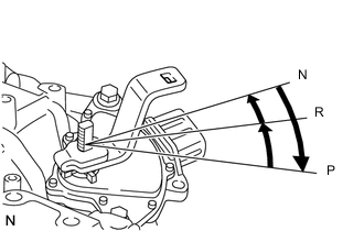
Turn the lever clockwise until it stops, and then turn it counterclockwise 2 notches.
-
Remove the control shaft lever.
-
Connect the park/neutral position switch connector.
Note
-
Before installing the park/neutral position switch assembly, remove any dirt or rust on the installation portion of the control shaft. Be sure to install the switch straight along the shaft while being careful not to deform the plate spring that supports the shaft. If the plate spring is deformed, the park/neutral position switch cannot be reinstalled correctly.
-
After installing the park/neutral position switch assembly, confirm that the 2 protrusions on the switch are aligned.
-
-
-
ADJUST PARK/NEUTRAL POSITION SWITCH ASSEMBLY
-
CONNECT TRANSMISSION CONTROL CABLE ASSEMBLY
-
Install the control shaft lever to the park/neutral position switch assembly with the nut and washer.
- Torque:
- 12.7 N*m { 130 kgf*cm, 9 ft.*lbf }
-
Connect the transmission control cable assembly to the control shaft lever with the nut.
- Torque:
- 12 N*m { 122 kgf*cm, 9 ft.*lbf }
-
-
INSTALL AIR CLEANER BRACKET
-
Install the air cleaner bracket with the 3 bolts.
- Torque:
- 7.5 N*m { 76 kgf*cm, 66 in.*lbf }
-
Attach the 2 fuel hoses to the air cleaner bracket.
-
Attach the 3 wire harness clamps.
-
Connect the glow relay.
-
Install the air cleaner support with the 2 nuts.
- Torque:
- 7.0 N*m { 71 kgf*cm, 62 in.*lbf }
-
-
CONNECT FUEL FILTER ASSEMBLY
-
Slide the fuel filter downward to connect it to the air cleaner bracket.
-
Install the bolt.
- Torque:
- 7.0 N*m { 71 kgf*cm, 62 in.*lbf }
-
Attach the level warning switch connector clamp.
-
Connect the connector.
-
-
INSTALL AIR CLEANER CASE SUB-ASSEMBLY
-
INSTALL AIR CLEANER FILTER ELEMENT SUB-ASSEMBLY
-
INSTALL AIR CLEANER CAP AND HOSE
-
INSTALL NO. 1 ENGINE COVER
-
INSPECT SHIFT LEVER POSITION