AUTOMATIC TRANSAXLE SYSTEM ECU Power Source Circuit
DESCRIPTION
When the ignition switch is turned to ON, voltage from the MREL terminal of the ECM is applied to the EFI-MAIN NO. 1 relay. This causes the contacts of the EFI-MAIN NO. 1 relay to close, which supplies power to terminal +B of the TCM.
WIRING DIAGRAM
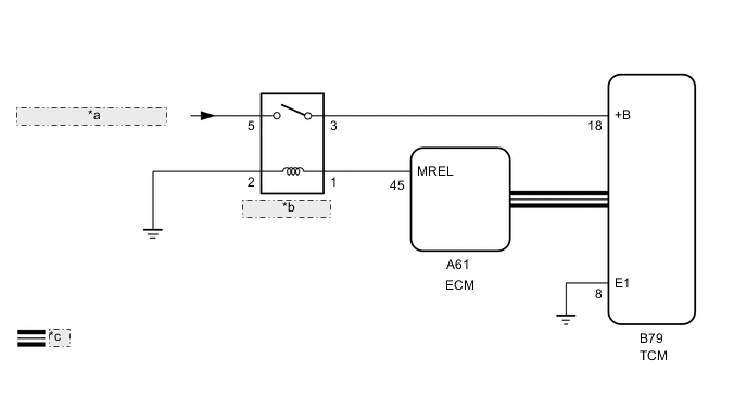
| *a | from EFI-MAIN NO. 1 Fuse |
| *b | EFI-MAIN NO. 1 |
| *c | CAN Communication Line |
CAUTION / NOTICE / HINT
Note
Inspect the fuses for circuits related to this system before performing the following inspection procedure.
PROCEDURE
-
CHECK HARNESS AND CONNECTOR (TCM - BODY GROUND)
-
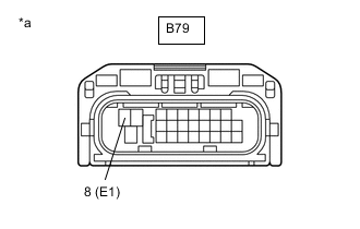
*a Front view of wire harness connector
(to TCM)
Disconnect the TCM connector.
-
Measure the resistance according to the value(s) in the table below.
Standard Resistance Tester Connection Condition Specified Condition B79-8 (E1) - Body ground Always Below 1 Ω Result Proceed to OK NG
NG 
REPAIR OR REPLACE HARNESS OR CONNECTOR
OK 
-
-
INSPECT ECU TERMINAL VOLTAGE (+B TERMINAL)
-
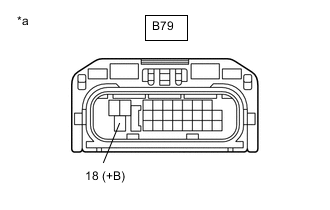
*a Front view of wire harness connector
(to TCM)
Disconnect the TCM connector.
-
Turn the ignition switch to ON.
-
Measure the voltage according to the value(s) in the table below.
Standard Voltage Tester Connection Switch Condition Specified Condition B79-18 (+B) - Body ground Ignition switch ON 11 to 14 V Result Proceed to OK NG
OK
PROCEED TO NEXT SUSPECTED AREA SHOWN IN PROBLEM SYMPTOMS TABLE Click here
NG
-
-
CHECK HARNESS AND CONNECTOR (EFI-MAIN NO. 1 RELAY - TCM)
-
Remove the EFI-MAIN NO. 1 relay from the engine room relay block and junction block assembly.
-
Disconnect the B79 TCM connector.
-
Measure the resistance according to the value(s) in the table below.
Standard Resistance Tester Connection Condition Specified Condition 3 (EFI-MAIN NO. 1 relay) - B79-18 (+B) Always Below 1 Ω 3 (EFI-MAIN NO. 1 relay) or B79-18 (+B) - Body ground Always 10 kΩ or higher Result Proceed to OK NG
OK
GO TO ECD SYSTEM (ECM POWER SOURCE CIRCUIT) for 2AD-FTV: Click here for 2AD-FHV: Click here
NG
REPAIR OR REPLACE HARNESS OR CONNECTOR
-