RADIATOR INSTALLATION
PROCEDURE
-
INSTALL FAN SHROUD
-
Install the fan shroud with the 3 bolts.
- Torque:
- 5.5 N*m { 56 kgf*cm, 49 in.*lbf }
-
-
INSTALL INTERCOOLER ASSEMBLY
-
INSTALL LOWER RADIATOR SUPPORT
-
INSTALL OIL COOLER TUBE SUB-ASSEMBLY (for Automatic Transaxle)
-
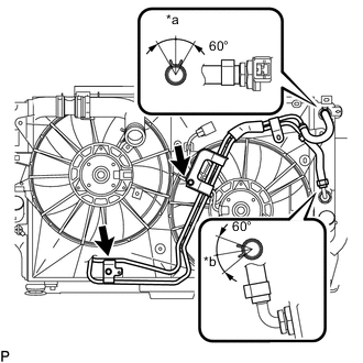
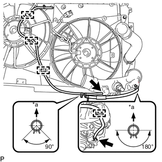
*a Top *b RH Side Connect the 2 hoses of the oil cooler hose tube sub-assembly to the radiator assembly and slide the 2 clips to secure the hose.
Tech Tips
Position the clips as illustrated.
-
Install the oil cooler tube sub-assembly with the 2 bolt.
- Torque:
- 5.5 N*m { 56 kgf*cm, 49 in.*lbf }
-
-
INSTALL NO. 2 RADIATOR HOSE
-
Install the No. 2 radiator hose to the radiator assembly and slide the clamp to secure the hose.
Tech Tips
Position the clamp as illustrated.
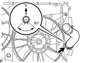
*a Top
-
-
INSTALL RADIATOR HOSE SUB-ASSEMBLY
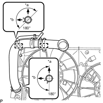
*a Top *b LH Side
-
Install the radiator hose sub-assembly to the radiator assembly, and slide the 2 clamps to secure the hose.
Tech Tips
Position the clamps as illustrated.
-
Attach the 2 clamps to the fan shroud.
-
-
INSTALL NO. 2 AIR TUBE
-
Install the No. 2 air tube to the intercooler assembly with the bolt.
Note
Before installation, remove any oil residue from the inside of the No. 2 air tube and intercooler assembly.
- Torque:
- 31 N*m { 316 kgf*cm, 23 ft.*lbf }
-
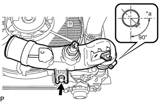
*a LH Side Tighten the hose clamp.
- Torque:
- 6.5 N*m { 66 kgf*cm, 58 in.*lbf }
Tech Tips
Position the clamp as illustrated.
-
-
INSTALL NO. 2 VACUUM TRANSMITTING HOSE ASSEMBLY
-
*a Top Attach the 4 clamps to the fan shroud and No. 2 air tube.
-
Install the No. 2 vacuum transmitting hose assembly to the intercooler assembly and No. 2 air hose and 2 clips to secure the hose.
Tech Tips
Position the clips as illustrated.
-
-
INSTALL COOLER CONDENSER ASSEMBLY
-
Install the cooler condenser assembly.
-
-
INSTALL NO. 2 RADIATOR SUPPORT
-
Install the 2 No. 2 radiator supports with the 4 bolts.
- Torque:
- 5.5 N*m { 56 kgf*cm, 49 in.*lbf }
-
-
INSTALL RADIATOR ASSEMBLY
-
Install the 2 cushions.
-
Insert the radiator assembly.
-
*a Top *b Paint Mark *c Front Side of Vehicle for Automatic Transaxle
-
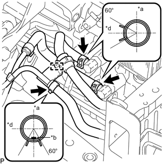
Connect the 3 oil cooler hoses to the automatic transaxle, and slide the 3 clips to secure the hose.
Tech Tips
Position the clips as illustrated.
-
Attach the clamp to the oil cooler tube sub-assembly.
-
-
-
INSTALL NO. 3 AIR HOSE
-
INSTALL INTERCOOLER AIR HOSE
Note
Before installation, remove any oil residue from the inside of the intercooler air hose.
-
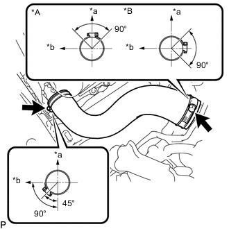
*A for Manual Transaxle *B for Automatic Transaxle *a Top *b LH Side Install the intercooler air hose to the No. 1 air tube and intercooler assembly and tighten the 2 hose clamps.
- Torque:
- 6.5 N*m { 66 kgf*cm, 58 in.*lbf }
Tech Tips
Position the hose clamps as illustrated.
-
-
CONNECT NO. 2 RADIATOR HOSE
-
CONNECT RADIATOR HOSE SUB-ASSEMBLY
-
INSTALL UPPER RADIATOR SUPPORT
-
Install the upper radiator support with the 4 bolts.
- Torque:
- 31 N*m { 316 kgf*cm, 23 ft.*lbf }
-
-
INSTALL HOOD LOCK ASSEMBLY
-
for LHD
-
for RHD
-
-
CONNECT WIRE HARNESS
-
Connect the 4 connectors to the fan motors, hood courtesy switch and intake air temperature sensor.
-
Attach the 13 clamps to the fan shroud.
-
-
CONNECT NO. 1 WATER BY-PASS HOSE
-
Connect the No. 1 water by-pass hose clamp bracket to the upper radiator support with the 2 bolts.
- Torque:
- 5.0 N*m { 51 kgf*cm, 44 in.*lbf }
-
Attach the hose clamp to the upper radiator support.
-
Connect the No. 1 water by-pass hose to the radiator reservoir assembly, and radiator hose sub-assembly and slide the 2 clamps to secure the hose.
-
-
INSTALL NO. 1 RADIATOR SUPPORT
-
Install the 2 radiator support cushions.
-
Install the 2 No. 1 radiator supports with the 2 bolts.
- Torque:
- 19 N*m { 194 kgf*cm, 14 ft.*lbf }
-
-
CONNECT NO. 2 VACUUM TRANSMITTING HOSE ASSEMBLY
-
Connect the No. 2 vacuum transmitting hose assembly, and slide the clip secure the hose.
-
-
INSTALL REAR RADIATOR SIDE AIR GUIDE PLATE LH
-
Install the rear radiator side air guide plate LH with the 2 clips.
-
-
INSTALL FRONT RADIATOR SIDE AIR GUIDE PLATE LH
-
Install the front radiator side air guide plate LH and attach the 3 claws.
-
-
INSTALL REAR RADIATOR SIDE AIR GUIDE PLATE RH
-
Install the rear radiator side air guide plate RH with the 2 clips.
-
-
INSTALL FRONT RADIATOR SIDE AIR GUIDE PLATE RH
-
Install the front radiator side air guide plate RH and attach the 3 claws.
-
-
CONNECT LIQUID TUBE SUB-ASSEMBLY
-
Remove the attached vinyl tape from the liquid tube sub-assembly and connecting part of the cooler condenser assembly.
-
Sufficiently apply compressor oil to a new O-ring and the fitting surface of the tube joint.
Compressor Oil ND-OIL 8 or equivalent -
Connect the liquid tube sub-assembly to the cooler condenser assembly with the bolt.
- Torque:
- 5.4 N*m { 55 kgf*cm, 48 in.*lbf }
-
-
CONNECT DISCHARGE HOSE SUB-ASSEMBLY
-
Remove the attached vinyl tape from the discharge hose sub-assembly and connecting part of the cooler condenser assembly.
-
Sufficiently apply compressor oil to a new O-ring and the fitting surface of the hose joint.
Compressor Oil ND-OIL 8 or equivalent -
Connect the discharge hose sub-assembly to the cooler condenser assembly with the bolt.
- Torque:
- 5.4 N*m { 55 kgf*cm, 48 in.*lbf }
-
-
INSTALL FRONT BUMPER REINFORCEMENT
-
CONNECT AMBIENT TEMPERATURE SENSOR ASSEMBLY
-
Attach the clamp to connect the ambient thermistor assembly.
-
-
INSTALL LOWER RADIATOR AIR GUIDE PLATE
-
Install the lower radiator guide plate and attach the 3 claws.
-
-
INSTALL UPPER RADIATOR AIR GUIDE PLATE
-
Install the upper radiator air guide plate with 6 clips.
-
-
INSTALL FRONT BUMPER UPPER REINFORCEMENT SUB-ASSEMBLY
-
Install the front bumper upper reinforcement sub-assembly with the 2 bolts.
-
-
INSTALL FRONT BUMPER CENTER STAY SUB-ASSEMBLY
-
Install the front bumper center stay sub-assembly with the 2 bolts and clip.
-
-
INSTALL LOW PITCHED HORN ASSEMBLY
-
INSTALL HIGH PITCHED HORN ASSEMBLY
-
INSTALL BATTERY BRACKET REINFORCEMENT
-
INSTALL FRONT BATTERY BRACKET
-
INSTALL BATTERY TRAY
-
INSTALL BATTERY
-
INSTALL BATTERY INSULATOR
-
INSTALL BATTERY CLAMP SUB-ASSEMBLY
-
INSTALL FRONT LOWER BUMPER ABSORBER
-
Install the front lower bumper absorber with the 4 screws.
-
-
INSTALL HEADLIGHT ASSEMBLY
-
for Halogen Headlight
-
for HID Headlight
-
-
INSTALL FRONT BUMPER COVER
-
CONNECT CABLE TO POSITIVE BATTERY TERMINAL
-
CONNECT CABLE TO NEGATIVE BATTERY TERMINAL
Note
When disconnecting the cable, some systems need to be initialized after the cable is reconnected.
-
ADD ENGINE COOLANT
-
CHARGE REFRIGERANT
-
WARM UP ENGINE
-
INSPECT FOR REFRIGERANT LEAK
-
ADJUSTMENT AUTOMATIC TRANSAXLE FLUID (for Automatic Transaxle)
-
INSPECT FOR COOLANT LEAK
-
INSTALL NO. 1 ENGINE COVER
-
INSTALL NO. 1 ENGINE UNDER COVER