EGR VALVE INSTALLATION
PROCEDURE
-
INSTALL ELECTRIC EGR CONTROL VALVE ASSEMBLY
-
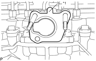
*1 Protrusion Install a new gasket.
Note
Make sure the protrusion of the gasket is facing upward as shown in the illustration.
-
Install the electric EGR control valve assembly.
-
-
INSTALL NO. 2 EGR PIPE SUB-ASSEMBLY
-
Install a new gasket to the No. 2 EGR pipe sub-assembly.
Tech Tips
Make sure that the claw of the gasket faces the No. 2 EGR pipe sub-assembly.
-
Install a new gasket to the electric EGR control valve assembly.
-
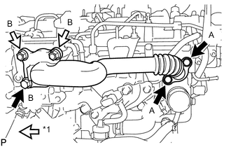
*1 Nut Temporarily install the No. 2 EGR pipe sub-assembly with the 3 bolts and 2 nuts.
Bolt Length Item Specified Condition Bolt A 25 mm (0.984 in.) Bolt B 70 mm (2.76 in.) -
Tighten the 2 bolts labeled A shown in the illustration.
- Torque:
- 24 N*m { 245 kgf*cm, 18 ft.*lbf }
-
Tighten the bolt and 2 nuts labeled B shown in the illustration.
- Torque:
- 24 N*m { 245 kgf*cm, 18 ft.*lbf }
-
Connect the electric EGR control valve connector.
-
-
CONNECT NO. 8 WATER BY-PASS HOSE
-
Connect the No. 8 water by-pass hose to the electric EGR control valve assembly, and slide the clamp to secure the hose.
-
-
CONNECT NO. 7 WATER BY-PASS HOSE
-
Connect the No. 7 water by-pass hose to the electric EGR control valve assembly, and slide the clamp to secure the hose.
-
-
INSTALL EGR VALVE BRACKET
-
Install the EGR valve bracket with the 3 bolts.
- Torque:
- 24 N*m { 245 kgf*cm, 18 ft.*lbf }
-
Connect the 2 connectors and attach the 2 wire harness clamps.
-
-
ADD ENGINE COOLANT
-
INSPECT FOR COOLANT LEAK
-
INSTALL NO. 1 ENGINE UNDER COVER
-
INSTALL NO. 1 ENGINE COVER
-
PERFORM ELECTRIC EGR CONTROL VALVE FULLY CLOSED POSITION LEARNING
Tech Tips
Be sure to turn off the ignition switch before performing this operation.
-
Turn the ignition switch to ON.
-
Turn the ignition switch off and wait 30 seconds.
Tech Tips
The fully closed position of the electric EGR control valve assembly is learned when the ignition switch is turned off.
-