FUEL SUPPLY PUMP REMOVAL
PROCEDURE
-
PRECAUTION
Note
-
After the engine has stopped, wait at least 1 minute before releasing the high pressure lines.
-
When working on the fuel circuit, protect the generator assembly against contamination. Cover the generator assembly with suitable materials. Failure to comply with this procedure may result in a generator assembly malfunction.
-
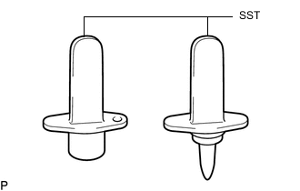
After disconnecting the pressure line, it is absolutely essential to seal the injector assemblies and the common rail assembly with SST.
SST PZ4TB-04941-79 -
The position of the fuel supply pump assembly in relation to the valve gear does not affect its function. However, it must be taken into account during removal and installation.
-
-
REMOVE FUEL INLET PIPE SUB-ASSEMBLY
-
SET NO. 1 CYLINDER TO TDC/COMPRESSION
Note
Set the No. 1 cylinder to TDC/compression so that the fuel supply pump assembly can be removed.
-
REMOVE NO. 1 AND NO. 2 FUEL HOSE PROTECTOR
-
Detach the clamp to disconnect the fuel temperature sensor connector.
-
Remove the bolt and No. 1 fuel hose protector from the No. 2 fuel hose protector.
-
Remove the No. 2 fuel hose protector from the fuel feed line hose and fuel return line hose.
-
-
REMOVE FUEL SUPPLY PUMP ASSEMBLY
Note
Do not remove SST A from the injection pump drive gear until all repair work has been completed.
-
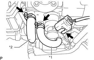
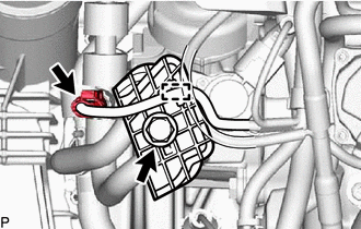
*1 Fuel Feed Line Hose *2 Fuel Return Line Hose Disconnect the fuel quantity control valve connector.
-
Loosen the 2 clamps and disconnect the fuel feed line hose and fuel return line hose from the fuel supply pump assembly.
-
Remove the 2 clamps from the fuel feed line hose and fuel return line hose.
-
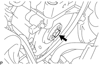
Remove the sealing cap from the timing chain cover plate.
-
Remove the O-ring from the sealing cap.
-
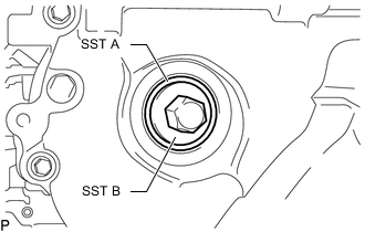
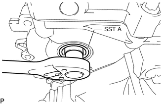
Using SST B, install SST A to position the fuel supply pump assembly. Then remove SST B.
SST PZ4TB-04967-25 Note
Do not remove SST A from the timing chain cover plate until all repair work has been completed.
-
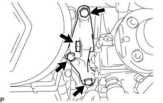
Remove the 4 bolts and fuel supply pump assembly support.
-
Remove the 2 bolts from the fuel supply pump assembly.
-
Loosen the central bolt connection between the fuel supply pump assembly and injection pump drive gear.
Note
-
Do not remove SST A from the timing chain cover plate.
-
The central bolt is supported on SST A until the fuel supply pump assembly is pressed out.
-
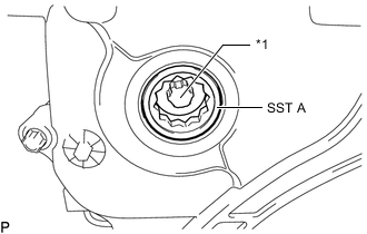
*1 Central Bolt The central bolt remains inside SST A attached to the injection pump drive gear.
-
-
Remove the fuel supply pump assembly from the cylinder block.
-
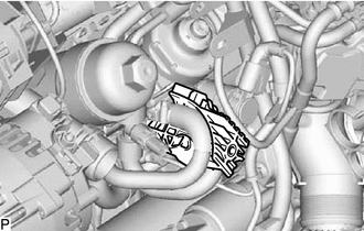
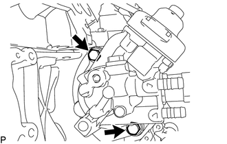
Remove the 2 bolts and fuel quantity control valve.
-