FUEL TANK INSTALLATION
PROCEDURE
-
INSTALL FUEL EMISSION HOSE
-
Install the fuel emission hose.
Note
-
Before connecting the fuel emission hose, check if there is any damage or foreign matter in the fuel emission hose or connector.
-
Check that the connector is connected by pulling on it.
Tech Tips
Firmly push the tube connector until a "click" sound is heard.
-
-
-
INSTALL CHARCOAL CANISTER OUTLET TUBE SUB-ASSEMBLY
-
Install the charcoal canister outlet tube sub-assembly to the fuel tank assembly and attach the 2 clamps.
-
-
INSTALL FUEL TUBE GROMMET
-
Install the 3 fuel tube grommets to the fuel tank assembly.
-
-
INSTALL NO. 5 FUEL TUBE CLAMP
-
Install the No. 5 fuel tube clamp to the fuel tank assembly.
-
-
INSTALL NO. 3 FUEL TUBE CLAMP
-
Install the No. 3 fuel tube clamp to the fuel tank assembly.
-
-
INSTALL NO. 1 FUEL EVAPORATION TUBE SUB-ASSEMBLY
-
Install the No. 1 fuel evaporation tube sub-assembly and attach the 5 clamps.
-
-
INSTALL FUEL TANK MAIN TUBE SUB-ASSEMBLY
-
Install the fuel tank main tube sub-assembly and attach the 5 clamps.
-
-
INSTALL FUEL SENDER GAUGE ASSEMBLY
-
INSTALL FUEL SUCTION TUBE ASSEMBLY WITH PUMP
-
INSTALL FUEL TANK VENT TUBE SET PLATE
-
CONNECT FUEL TANK MAIN TUBE SUB-ASSEMBLY
-
CONNECT FUEL EMISSION HOSE
-
INSTALL FUEL TANK ASSEMBLY
-
Set the fuel tank assembly on an engine lifter with attachments.
-
Lift up the engine lifter.
-
Attach the wire harness to the 3 clamps.
-
Connect the fuel pump connector and sender gauge connector.
Note
Be careful not to cut the wiring.
-
Install the No. 1 fuel tank band sub-assembly with the 2 bolts.
- Torque:
- 45 N*m { 459 kgf*cm, 33 ft.*lbf }
-
Install the No. 1 fuel tank band sub-assembly LH with the 2 bolts.
- Torque:
- 45 N*m { 459 kgf*cm, 33 ft.*lbf }
-
Install the No. 2 fuel tank band sub-assembly with the 2 bolts.
- Torque:
- 45 N*m { 459 kgf*cm, 33 ft.*lbf }
-
Attach the 3 wire harness clamps.
-
-
CONNECT NO. 3 FUEL TANK BREATHER TUBE SUB-ASSEMBLY
-
Connect the No. 3 fuel tank breather tube sub-assembly to the fuel tank.
-
-
CONNECT CHARCOAL CANISTER OUTLET TUBE SUB-ASSEMBLY
-
Connect the charcoal canister outlet tube sub-assembly to the fuel tank breather tube and slide the clamp to secure it.
-
Attach the hose clamp.
-
-
CONNECT FUEL TANK TO FILLER PIPE HOSE
-
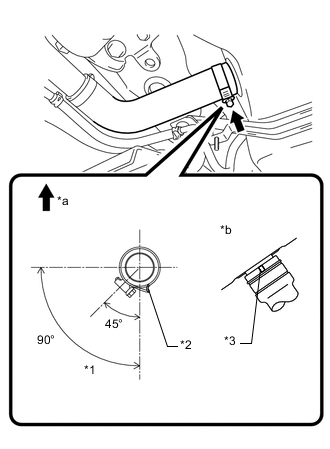
*1 Range *2 Stopper *3 Protrusion *a Top of Vehicle *b Bottom of Fuel Tank Connect the fuel tank to filler pipe hose to the fuel tank assembly and tighten the hose clamp.
Tech Tips
Make sure the hose clamp is oriented as shown in the illustration.
-
-
INSTALL FUEL HOSE PROTECTOR
-
Install the fuel hose protector to the fuel tank to filler pipe hose and attach the claw.
-
-
CONNECT NO. 1 FUEL EVAPORATION TUBE SUB-ASSEMBLY
-
Connect the No. 1 fuel evaporation tube sub-assembly and slide the clamp to secure it.
-
-
CONNECT FUEL TANK MAIN TUBE SUB-ASSEMBLY
-
Connect the fuel tank main tube sub-assembly.
-
-
INSTALL NO. 1 FUEL TANK PROTECTOR
-
Install the No. 1 fuel tank protector with the 2 bolts.
- Torque:
- 20 N*m { 204 kgf*cm, 15 ft.*lbf }
-
Install the 2 clips and grommet.
-
-
CONNECT PARKING BRAKE CABLE
-
Connect the parking brake cable with the 2 bolts.
- Torque:
- 6.0 N*m { 61 kgf*cm, 53 in.*lbf }
-
-
ADD FUEL
-
CONNECT CABLE TO NEGATIVE BATTERY TERMINAL
Note
When disconnecting the cable, some systems need to be initialized after the cable is reconnected.
-
INSPECT FOR FUEL LEAK