FUEL INJECTOR INSTALLATION

CAUTION / NOTICE / HINT
PROCEDURE
-
INSTALL FUEL INJECTOR ASSEMBLY
-
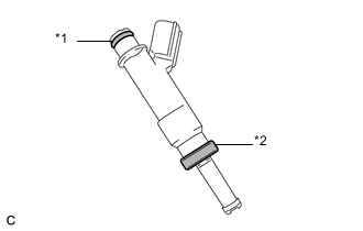
*1 O-Ring *2 Injector Vibration Insulator Install a new injector vibration insulator and a new O-ring to each fuel injector assembly.
-
Apply a light coat of gasoline or spindle oil to the O-ring of the fuel injector assembly.
-
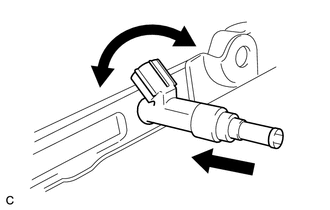
While turning the fuel injector assembly left and right, install it to the fuel delivery pipe sub-assembly.
Note
-
Do not twist the O-ring.
-
After installing the fuel injectors, check that they turn smoothly. If not, replace the O-ring with a new one.
-
-
-
INSTALL FUEL DELIVERY PIPE SUB-ASSEMBLY
-
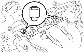
Install the 2 No. 1 delivery pipe spacers to the cylinder head.
Note
Install the No. 1 delivery pipe spacers in the correct direction.
-
Install the fuel delivery pipe sub-assembly with the 4 fuel injector assemblies, and then temporarily install the 2 bolts.
Note
-
Do not drop the fuel injector assemblies when installing the fuel delivery pipe sub-assembly.
-
Check that the fuel injector assemblies rotate smoothly after installing the fuel delivery pipe sub-assembly.
-
-
Tighten the 2 bolts to the specified torque.
- Torque:
- 21 N*m { 214 kgf*cm, 15 ft.*lbf }
-
Install the bolt to secure the fuel delivery pipe sub-assembly.
- Torque:
- 21 N*m { 214 kgf*cm, 15 ft.*lbf }
-
Install the wire harness bracket with the bolt.
- Torque:
- 8.0 N*m { 82 kgf*cm, 71 in.*lbf }
-
-
CONNECT FUEL TUBE SUB-ASSEMBLY
-
Connect the fuel tube sub-assembly, and then install a new No. 2 fuel pipe clamp.
-
-
INSTALL VACUUM SURGE TANK
-
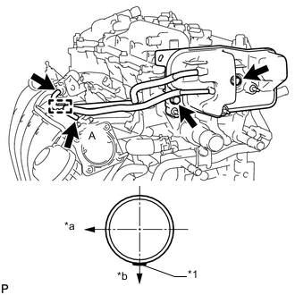
*1 Paint Mark *a Front Side of Vehicle *b LH Side Install the vacuum surge tank with the 2 bolts.
- Torque:
- 21 N*m { 214 kgf*cm, 15 ft.*lbf }
-
Connect the 2 air hoses to the purge VSV and intake manifold and attach the clamp.
Tech Tips
Connect the air hose labeled A so that the paint mark is positioned as shown in the illustration.
-
-
INSTALL AIR TUBE
-
Install the air tube with the 2 bolts.
- Torque:
- 10 N*m { 102 kgf*cm, 7 ft.*lbf }
-
Connect the No. 1 fuel vapor feed hose to the air tube.
-
Connect the No. 1 vacuum transmitting hose to the air tube and slide the clamp to secure it.
-
Connect the union to connector tube hose to the air tube and slide the clamp to secure it.
-
Connect the fuel vapor feed hose to the purge VSV and slide the clamp to secure it.
-
-
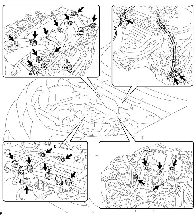
CONNECT ENGINE WIRE
-
Attach the 9 clamps and connect the 18 connectors.
-
Connect the engine wire with the 3 bolts and 3 nuts.
- Torque:
- for bolt A
- 7.7 N*m { 79 kgf*cm, 68 in.*lbf }
- for bolt B and nut
- 8.4 N*m { 86 kgf*cm, 74 in.*lbf }
-
-
INSTALL BATTERY TRAY
-
INSTALL BATTERY
-
INSTALL BATTERY CLAMP SUB-ASSEMBLY
-
INSTALL AIR CLEANER CASE SUB-ASSEMBLY
-
INSTALL AIR CLEANER CAP SUB-ASSEMBLY
-
CONNECT CABLE TO NEGATIVE BATTERY TERMINAL
Note
When disconnecting the cable, some systems need to be initialized after the cable is reconnected.
-
INSPECT FOR FUEL LEAK
-
Make sure that there are no fuel leaks after performing maintenance on the fuel system.
-
Connect the GTS to the DLC3.
-
Turn the ignition switch to ON, and GTS on.
Note
Do not start the engine.
-
Enter the following menus: Powertrain / Engine and ECT / Active Test / Control the Fuel Pump / Speed.
Powertrain > Engine and ECT > Active TestTester Display Control the Fuel Pump / Speed -
Check that there are no leaks from the fuel system.
-
Turn the ignition switch off.
-
Disconnect the GTS from the DLC3.
-
-
-
INSTALL NO. 2 CYLINDER HEAD COVER