FUEL INJECTOR INSTALLATION

CAUTION / NOTICE / HINT
Tech Tips
Perform "Inspection After Repairs" after replacing the fuel injector assembly.
-
w/ Canister Pump Module
-
w/o Canister Pump Module
PROCEDURE
-
INSTALL FUEL INJECTOR ASSEMBLY
Tech Tips
Perform "Inspection After Repairs" after replacing the fuel injector assembly.
-
w/ Canister Pump Module
-
w/o Canister Pump Module
-
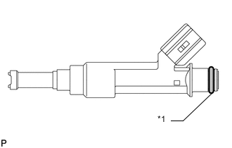
*1 New O-Ring Apply a light coat of gasoline or spindle oil to new O-rings, and then install one to each fuel injector assembly.
-
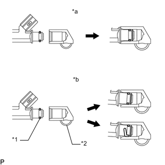
*1 O-Ring *2 Fuel Delivery Pipe *a CORRECT *b INCORRECT Apply a light coat of gasoline or spindle oil to the part of the fuel delivery pipe which comes into contact with the O-ring of the fuel injector assembly.
-
Apply a light coat of gasoline or spindle oil to the O-ring again, and then install the fuel injector assemblies to the fuel delivery pipe.
Note
Make sure that the O-ring is not cracked or jammed when installing the injector assembly.
-
Check that the fuel injector assembly rotates smoothly. If the fuel injector assembly does not rotate, replace the O-ring.
-
-
INSTALL FUEL DELIVERY PIPE
-
Install 4 new injector vibration insulators to the cylinder head.
-
Install the 2 fuel delivery spacers to the cylinder head.
-
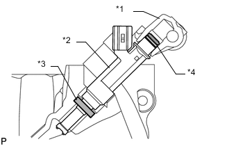
*1 Fuel Delivery Pipe *2 Fuel Injector Assembly *3 Fuel Vibration Insulator *4 O-Ring Install the fuel delivery pipe together with the 4 fuel injector assemblies to the cylinder head, and then temporarily install the 2 bolts.
Note
Be careful not to drop the fuel injector assemblies when installing the fuel delivery pipe.
-
Check that the fuel injector assembly rotates smoothly.
If the fuel injector assembly does not rotate, replace the O-ring.
-
Tighten the 2 bolts to the specified torque.
- Torque:
- 21 N*m { 214 kgf*cm, 15 ft.*lbf }
-
-
CONNECT WIRE HARNESS
-
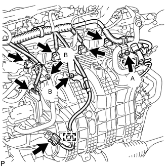
Attach the clamp to connect the wire harness.
-
Install the 3 wire harness brackets with the 3 bolts.
- Torque:
- for bolt A
- 9.0 N*m { 92 kgf*cm, 80 in.*lbf }
- for bolt B
- 10 N*m { 102 kgf*cm, 7 ft.*lbf }
-
Connect the 2 connectors.
-
Connect the 4 fuel injector connectors.
-
-
CONNECT FUEL TUBE SUB-ASSEMBLY
-
Connect the fuel tube sub-assembly and install a new No. 2 fuel pipe clamp.
-
-
CONNECT FUEL HOSE BRACKET
-
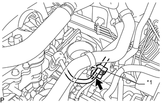
*1 Clamp Connect the fuel hose bracket with the bolt.
- Torque:
- 13 N*m { 133 kgf*cm, 10 ft.*lbf }
Note
If the fuel hose is detached from the clamp shown in the illustration, the clamp cannot be reused.
-
-
INSTALL AIR CLEANER CAP SUB-ASSEMBLY
-
INSTALL NO. 1 ENGINE COVER SUB-ASSEMBLY
-
CONNECT CABLE TO NEGATIVE BATTERY TERMINAL
Note
When disconnecting the cable, some systems need to be initialized after the cable is reconnected.
-
INSPECT FOR FUEL LEAK
-
Make sure that there are no fuel leaks after performing maintenance on the fuel system.
-
Connect the GTS to the DLC3.
-
Turn the ignition switch to ON, and then turn the GTS on.
Note
Do not start the engine.
-
w/ Fuel Pump Control ECU
Enter the following menus: Powertrain / Engine and ECT / Active Test / Control the Fuel Pump / Speed.
Powertrain > Engine and ECT > Active TestTester Display Control the Fuel Pump / Speed -
w/o Fuel Pump Control ECU
Enter the following menus: Powertrain / Engine and ECT / Active Test / Control the Fuel Pump / Speed.
Powertrain > Engine and ECT > Active TestTester Display Control the Fuel Pump / Speed -
Check that there are no leaks from the fuel system.
If there are fuel leaks, repair or replace parts as necessary.
-
Turn the ignition switch off.
-
Disconnect the GTS from the DLC3.
-
-