FUEL INJECTOR REMOVAL
CAUTION / NOTICE / HINT
Note
-
When replacing the injector assemblies (including shuffling the injector assemblies between the cylinders), common rail assembly, intake manifold or cylinder head sub-assembly, it is necessary to replace the injection pipes with new ones.
-
When replacing the fuel supply pump assembly, common rail assembly, intake manifold or cylinder head sub-assembly, it is necessary to replace the fuel inlet pipe sub-assembly with a new one.
PROCEDURE
-
PRECAUTION
Note
After turning the ignition switch off, waiting time may be required before disconnecting the cable from the battery terminal. Therefore, make sure to read the disconnecting the cable from the battery terminal notice before proceeding with work.
-
DISCONNECT CABLE FROM NEGATIVE BATTERY TERMINAL
Note
When disconnecting the cable, some systems need to be initialized after the cable is reconnected.
-
REMOVE NO. 1 ENGINE COVER
-
REMOVE AIR CLEANER CAP SUB-ASSEMBLY
-
REMOVE AIR CLEANER FILTER ELEMENT SUB-ASSEMBLY
-
REMOVE AIR CLEANER CASE
-
DISCONNECT ENGINE WIRE
-
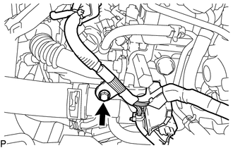
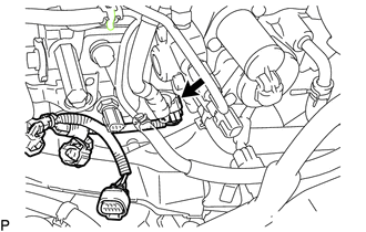
Remove the bolt from the wire harness bracket.
-
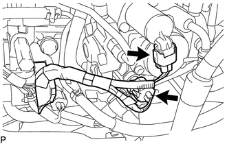
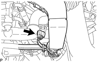
Disconnect the fuel temperature sensor connector and suction control valve connector.
-
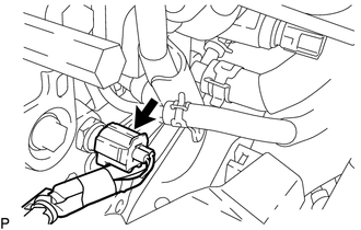
Disconnect the engine coolant temperature sensor.
-
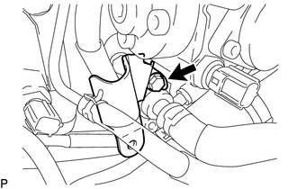
for DPF:
Detach the clamp and remove the bolt and fuel hose protector.
-
for DPF:
Disconnect the exhaust fuel addition injector connector.
-
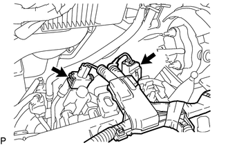
Disconnect the No. 1 vacuum switching valve connector and vacuum regulating valve connector.
-
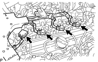
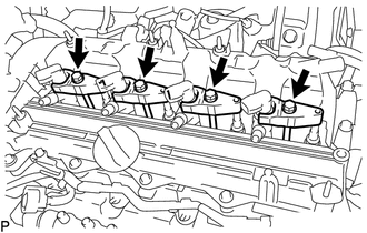
Disconnect the 4 fuel injector connectors.
-
Remove the No. 1 screw grommet and nut, and disconnect the glow plug wire harness.
-
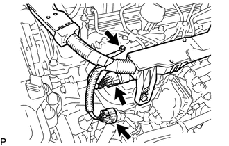
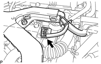
Disconnect the fuel pressure sensor connector and electric EGR control valve connector.
-
Disconnect the diesel turbo pressure sensor connector.
-
Disconnect the pressure discharge valve connector.
-
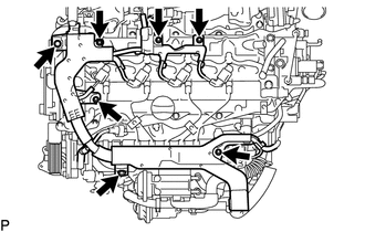
Remove the 2 bolts and 5 nuts and disconnect the engine wire.
-
-
REMOVE INJECTION PIPE SUB-ASSEMBLY
Note
After removing the injection pipe, cover the common rail with electrical tape to prevent dirt or foreign objects from entering the pipe inlet. Also, protect the injector inlets with electrical tape or plastic bags.
-
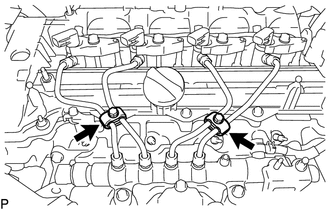
Remove the 2 bolts and 4 No. 2 injection pipe clamps.
-
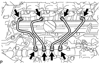
Using a 14 mm union nut wrench, loosen the 8 union nuts and remove the injection pipe sub-assemblies.
-
-
REMOVE FUEL HOSE PROTECTOR (for DPF)
-
REMOVE FUEL TUBE SUB-ASSEMBLY (for DPF)
-
REMOVE NO. 2 FUEL PIPE (for CCo)
-
REMOVE NO. 2 NOZZLE LEAKAGE PIPE
-
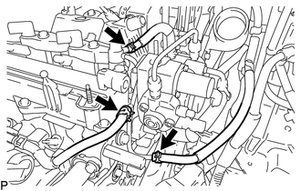
Slide the 3 clamps and disconnect the No. 2 fuel hose, No. 3 fuel hose and No. 4 fuel hose from the No. 2 nozzle leakage pipe.
-
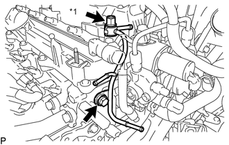
*1 Check Valve Remove the check valve and gasket.
-
Remove the bolt and No. 2 nozzle leakage pipe.
-
-
REMOVE NO. 1 NOZZLE LEAKAGE PIPE
-
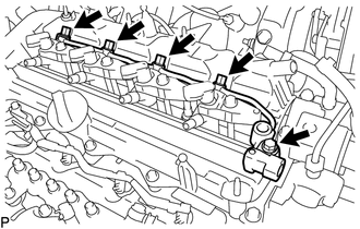
Remove the 4 union bolts and 4 gaskets.
-
Remove the bolt and No. 1 nozzle leakage pipe.
-
-
REMOVE NO. 1 NOZZLE HOLDER CLAMP
-
Remove the 4 nozzle holder clamp bolts, 4 washers and 4 No. 1 nozzle holder clamps.
-
-
REMOVE INJECTOR ASSEMBLY
-
Remove the 4 injector assemblies and 4 injection nozzle seats from the cylinder head sub-assembly.
-
Remove the O-ring from each injector assembly.
Note
When removing the injector assembly, store the injector assemblies in the correct order so that they can be returned to their original locations when reassembling.
-