FUEL INJECTOR INSTALLATION
CAUTION / NOTICE / HINT
Note
-
When replacing the injector assemblies (including shuffling the injector assemblies between the cylinders), common rail assembly, intake manifold or cylinder head sub-assembly, it is necessary to replace the injection pipes with new ones.
-
When replacing the fuel supply pump assembly, common rail assembly, intake manifold or cylinder head sub-assembly, it is necessary to replace the fuel inlet pipe sub-assembly with a new one.
PROCEDURE
-
INSTALL INJECTOR ASSEMBLY
Note
Before installing the injector assembly, check for carbon, foreign matter, etc. on the seal surfaces of the cylinder head and injector assembly. If there is foreign matter, remove it before installing the injector assembly.
-
Install 4 new injection nozzle seats to the cylinder head sub-assembly.
-
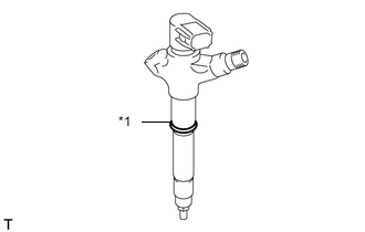
*1 New O-Ring Install a new O-ring to each injector assembly.
-
Apply a light coat of engine oil to the O-ring on each injector assembly.
-
Install the 4 injector assemblies to the cylinder head sub-assembly.
Note
Fit the injector assembly to the injection nozzle seats.
-
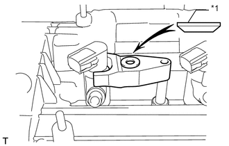
*1 Washer Install the nozzle holder clamps and washers as shown in the illustration.
Note
Pay attention to the mounting orientation (beveled edge) of the washer.
-
Temporarily install the No. 1 nozzle holder clamp bolts.
Note
When temporarily installing the No. 1 nozzle holder clamp bolt to the No. 1 nozzle holder clamp, make sure that the bolt and clamp are not at an angle.
Tech Tips
Apply a light coat of engine oil to the threads of the No. 1 nozzle holder clamp bolts.
-
Temporarily install the 4 injection pipes.
-
Temporarily install the No. 1 nozzle leakage pipe and 4 new gaskets with the 4 union bolts and bolt.
-
Tighten the 4 nozzle holder clamp bolts.
- Torque:
- 25 N*m { 255 kgf*cm, 18 ft.*lbf }
-
Tighten the 4 union bolts of the No. 1 nozzle leakage pipe.
- Torque:
- 18 N*m { 184 kgf*cm, 13 ft.*lbf }
-
Tighten the bolt of the No. 1 nozzle leakage pipe.
- Torque:
- 21 N*m { 209 kgf*cm, 15 ft.*lbf }
-
-
INSTALL FUEL TUBE SUB-ASSEMBLY
-
INSTALL FUEL HOSE PROTECTOR
-
INSTALL INJECTION PIPE SUB-ASSEMBLY
-
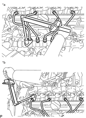
*a Common Rail Assembly Side *b Injector Assembly Side Using a 14 mm union nut wrench, tighten the 4 injection pipe union nuts on the common rail assembly side.
- Torque:
- 30 N*m { 306 kgf*cm, 22 ft.*lbf }
Note
Use the formula to calculate special torque values for situations where a union nut wrench is combined with a torque wrench.
-
Using a 14 mm union nut wrench, tighten the 4 injection pipe union nuts on the injector assembly side.
- Torque:
- 30 N*m { 306 kgf*cm, 22 ft.*lbf }
Note
Use the formula to calculate special torque values for situations where a union nut wrench is combined with a torque wrench.
-
Install the 4 No. 2 injection pipe clamps with the 2 bolts.
- Torque:
- 5.0 N*m { 51 kgf*cm, 44 in.*lbf }
-
-
INSTALL NO. 2 NOZZLE LEAKAGE PIPE
-
Temporarily install the No. 2 nozzle leakage pipe and a new gasket with the check valve and bolt.
-
Tighten the check valve.
- Torque:
- 32 N*m { 321 kgf*cm, 23 ft.*lbf }
-
Tighten the bolt.
- Torque:
- 32 N*m { 321 kgf*cm, 23 ft.*lbf }
-
Connect the No. 2 fuel hose, No. 3 fuel hose and No. 4 fuel hose to the No. 2 Nozzle leakage pipe, and slide the 3 clamps to secure the hoses.
-
-
CONNECT ENGINE WIRE
-
Connect the engine wire with the 2 bolts and 5 nuts.
- Torque:
- 7.65 N*m { 78 kgf*cm, 68 in.*lbf }
-
Connect the pressure discharge valve connector.
-
Connect the diesel turbo pressure sensor connector.
-
Connect the fuel pressure sensor connector and electric EGR control valve connector.
-
Connect the glow plug connector.
-
Connect the 4 fuel injector connectors.
-
Connect the No. 1 vacuum switching valve connector and exhaust gas temperature sensor connector.
-
Connect the exhaust fuel addition injector connector.
-
Install the fuel hose protector with the bolt and attach the clamp.
- Torque:
- 20.5 N*m { 209 kgf*cm, 15 ft.*lbf }
-
Connect the engine coolant temperature sensor connector and turbocharger connector.
-
Connect the fuel temperature sensor connector and suction control valve connector.
-
Install the bolt to the wire harness bracket.
- Torque:
- 7.65 N*m { 78 kgf*cm, 68 in.*lbf }
-
-
INSTALL AIR CLEANER CASE
-
INSTALL AIR CLEANER FILTER ELEMENT SUB-ASSEMBLY
-
INSTALL AIR CLEANER CAP SUB-ASSEMBLY
-
CONNECT CABLE TO NEGATIVE BATTERY TERMINAL
Note
When disconnecting the cable, some systems need to be initialized after the cable is reconnected.
-
PERFORM REGISTRATION
-
Perform registration of injector compensation codes.
-
Perform registration of pilot quantity learning.
-
-
BLEED AIR FROM FUEL SYSTEM
-
INSPECT FOR FUEL LEAK
-
INSTALL NO. 1 ENGINE COVER