ECD SYSTEM SYSTEM DESCRIPTION
-
ENGINE CONTROL SYSTEM
-
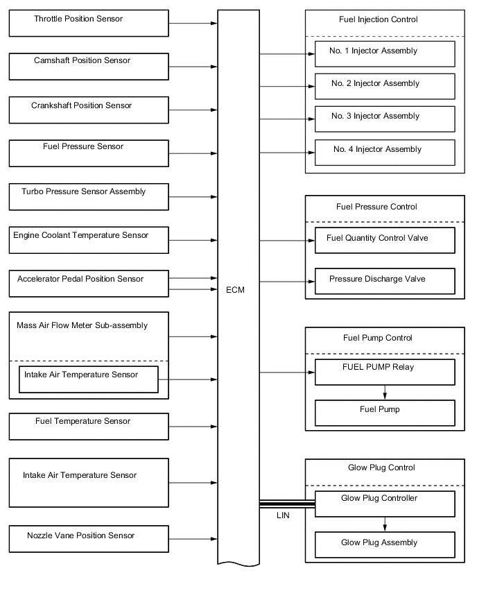
System Control Table
-
The engine control system of the 2WW engine has the following systems:
System Outline Fuel Injection Control Based on the signals received from the sensors, the ECM determines the fuel injection volume and fuel injection timing in accordance with the engine condition. Fuel Pressure Control Based on the signals received from the fuel pressure sensor, the ECM controls fuel pressure using the fuel quantity control valve and pressure discharge valve in accordance with engine operating conditions. Fuel Pump Control Fuel pump operation is controlled by signals from the ECM in order to feed fuel to the fuel supply pump assembly. Glow Plug Control
-
The ECM sends signals to the glow plug controller in accordance with engine conditions. Based on the signals, the glow plug controller controls the length of time for which the current is applied to the glow plug assemblies in each cylinder.
-
Detects individual disconnections of circuit wires and short circuits by the use of the glow plug controller.
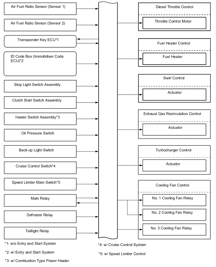
Diesel Throttle Control
-
Controls the diesel throttle valve opening angle in accordance with the engine condition.
-
Fully closes the diesel throttle valve in order to reduce vibration when the engine is stopped.
Swirl Control Based on the signals received from the sensors, the ECM controls the actuator (for swirl control), in order to open and close the valve. Turbocharger Control Based on the signals received from the sensors, the ECM controls the actuator in accordance with the engine condition. -
-
-
Fuel Injection Control
-
Based on information from various sensors, the ECM determines the injection timing and injection volume according to the engine condition, operates the fuel injectors and controls the fuel injection.
-
The types of fuel injection are as follows:
Fuel Injection Type Purpose Pre-injection Reduces combustion noise by gradually starting fuel combustion for the main injection. Main Injection Optimizes combustion by using optimal fuel injection. Post-injection
-
Activates the CCo catalyst.
-
Regenerates the Diesel Particulate Filter (DPF) catalyst.
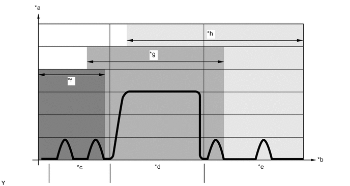
*a Nozzle Needle Stroke (mm) *b Time (msec.) *c Pre-injection *d Main Injection *e Post-injection *f Acoustic Optimization *g Combustion Optimization *h Exhaust Re-treatment -
-
-
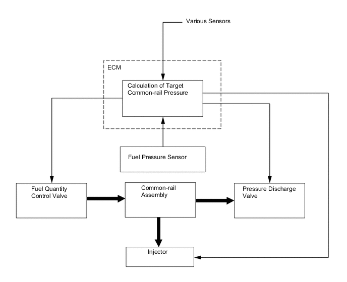
Fuel Pressure Control
-
The ECM calculates the target injection pressure based on the signals from the various sensors. To control fuel pressure, signals sent to the fuel quantity control valve of the supply pump assembly regulate the fuel flow volume, and signals sent to the pressure discharge valve of the common-rail regulate the discharge volume, so that the pressure detected by the fuel pressure sensor matches the target injection pressure.
-
-
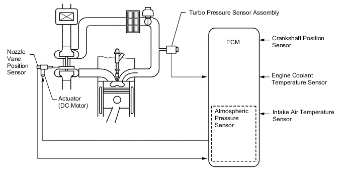
Turbocharger Control
-
The ECM calculates the optimal nozzle vane position in accordance with the driving conditions (engine speed, injection volume, atmospheric pressure, and engine coolant temperature etc.), and controls the nozzle vane position in accordance with the optimal nozzle vane position and the actual nozzle vane position signal from the nozzle vane position sensor.
-
-
Diesel Throttle Control
-
Diesel throttle control has following functions:
-
A function that closes the diesel throttle valve to reduce vibration and noise when the engine is being stopped.
-
A function that regulates the volume of intake air to maintain the exhaust gas temperature required to regenerate the Diesel Particulate Filter (DPF) catalyst.
-
A function that prevents the engine speed from increasing excessively when combustion materials other than those introduced during normal fuel injection have gotten into the cylinder.*
Tech Tips
*: For example, if engine oil flows from the turbocharger sub-assembly to the cylinder due to damage to the bearing.
-
-
-
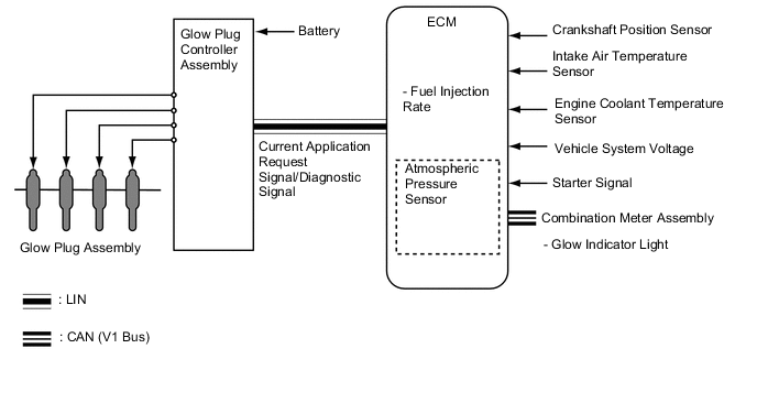
Glow Plug Control
-
The ECM sends a signal to the glow plug controller, and the glow plug controller independently controls the length of time for which the current is applied to the glow plug assemblies in each cylinder in accordance with engine conditions. By independently and precisely controlling the temperature inside each cylinder, low emissions are achieved.
-
-
-
EMISSION CONTROL SYSTEM
-
System Control Table
-
The emission control system of the 2WW engine has the following systems.
System Description Exhaust Gas Recirculation (EGR) Control Based on the signals received from the sensors, the ECM determines the EGR volume via the EGR valve and EGR cooler bypass switching valve in accordance with the engine condition. Diesel Particulate Filter (DPF) Catalyst Regeneration Control The ECM judges the DPF catalyst condition based on signals from the exhaust gas temperature sensor, differential pressure sensor and air fuel ratio sensor to control the diesel throttle control motor and injector assemblies for DPF catalyst regeneration control. Air Fuel Ratio Sensor Heater Control The ECM controls the air fuel ratio sensor heater according to the engine condition in order to promote the warm-up of the air fuel ratio sensor.
-
-
EGR Control
-
This system is designed to help reduce and control NOx formation due to a peak temperature reduction in the engine combustion chamber, which is accomplished by the introduction of amounts of inert gas into the intake manifold.
-
The ECM switches the bypass passage of the EGR cooler assembly via the EGR cooler bypass switching valve assembly in order to optimize the temperature of the EGR gas and clean exhaust gases.
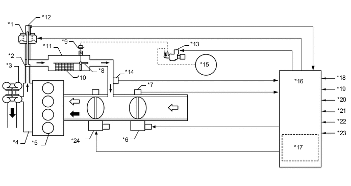
*1 EGR Valve Assembly *2 EGR Valve *3 Turbocharger Sub-assembly *4 Exhaust Manifold *5 Engine *6 Throttle Control Motor *7 Throttle Position Sensor *8 EGR Cooler Bypass Switching Valve *9 Actuator for EGR Cooler Bypass Switching Valve Assembly *10 EGR Cooler *11 EGR Cooler Assembly *12 EGR Valve Position Sensor *13 EGR Cooler Bypass Switching Valve Assembly *14 EGR Gas Temperature Sensor *15 Vacuum Pump *16 ECM *17 Atmospheric Pressure Sensor *18 Crankshaft Position Sensor *19 Accelerator Pedal Position Sensor *20 Engine Coolant Temperature Sensor *21 Turbo Pressure Sensor Assembly *22 Intake Air Temperature Sensor *23 Mass Air Flow Meter Sub-assembly *24 Swirl Control Valve 
Exhaust Gas 
Intake Air
-
-
Diesel Particulate Filter (DPF) Catalyst Regeneration Control
-
This control optimally regulates the fuel injection volume, fuel injection timing and opening of the diesel throttle valve in order to burn Particulate Matter (PM) captured in the DPF catalyst.
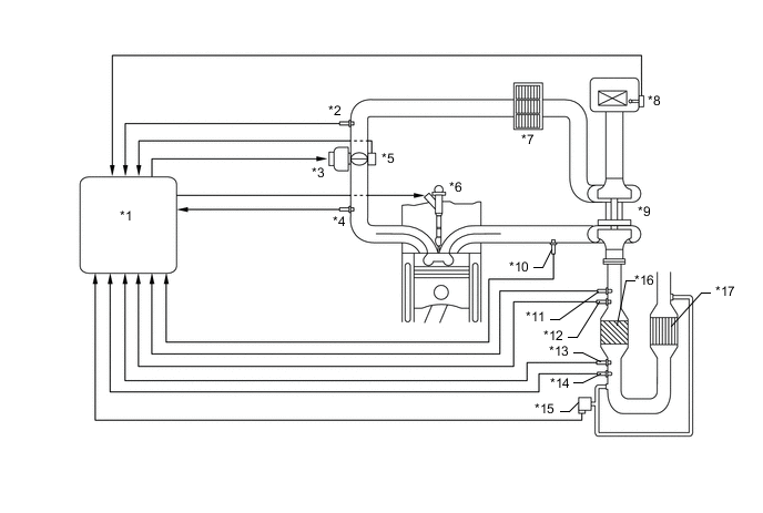
*1 ECM *2 Intake Air Temperature Sensor *3 Throttle Control Motor *4 Turbo Pressure Sensor Assembly *5 Throttle Position Sensor *6 Injector Assembly *7 Intercooler Assembly *8 Mass Air Flow Meter Sub-assembly *9 Turbocharger Sub-assembly *10 Exhaust Gas Pressure Sensor *11 Air Fuel Ratio Sensor (for Sensor 1) *12 Exhaust Gas Temperature Sensor (for Sensor 1) *13 Exhaust Gas Temperature Sensor (for Sensor 2) *14 Air Fuel Ratio Sensor (for Sensor 2) *15 Differential Pressure Sensor *16 NSR Catalyst *17 Diesel Particulate Filter (DPF) Catalyst - - -
The ECM judges the DPF catalyst condition based on signals from various sensors. When the ECM determines that PM has accumulated in the DPF catalyst, the ECM activates regeneration control.
-
To reduce PM, the ECM controls the injection timing and the injection frequency of the injectors. In addition, the ECM controls the opening of the diesel throttle valve to maintain the exhaust gas temperature required to burn PM.
-
At the same time, the filter substrate temperature becomes high and PM reacts with active oxygen and changes into CO2 for purification.
-
-
-
FUEL SYSTEM
-
Fuel System Description
-
In this system, the highly pressurized fuel supplied by the fuel supply pump assembly is stored in the common rail assembly, and the ECM sends signals to the injectors in order to control the injection timing and injection volume.
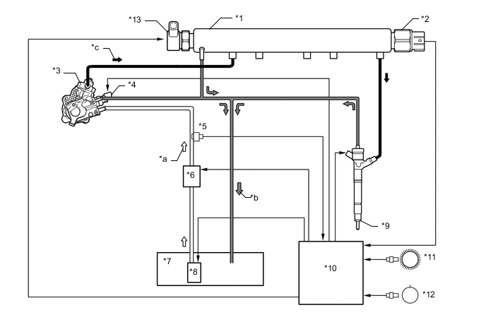
*1 Common Rail Assembly *2 Fuel Pressure Sensor *3 Fuel Supply Pump Assembly *4 Fuel Quantity Control Valve *5 Fuel Temperature Sensor *6 Fuel Filter Assembly
-
Fuel Heater
*7 Fuel Tank Assembly *8 Fuel Suction Tube with Pump and Gauge Assembly
-
Fuel Pump
*9 Injector Assembly *10 ECM *11 Crankshaft Position Sensor (NE Signal) *12 Camshaft Position Sensor (G Signal) *13 Pressure Discharge Valve - - *a Fuel (Low Pressure) *b Fuel (Return) *c Fuel (High Pressure) - - -
-
-
Fuel Supply Pump Assembly
-
The fuel fed from the fuel pump flows to the camshaft space. The fuel lubricates the fuel supply pump assembly through the bearing bush and returns to the fuel tank. In addition, excess fuel returns from the fuel over flow valve to the fuel tank.
-
The fuel in the camshaft space flows to the flow control valve in the fuel quantity control valve. The flow rate of the fuel which passes through the flow control valve is controlled and the fuel flows to the valve plate.
-
When the camshaft rotates and the plunger is pushed down due to the force of the tappet spring, the check valve is pushed down due to the fuel applied against the check valve spring or pulled down due to the downward movement of the plunger. As a result, the fuel can flow into the cylinder.
-
When the camshaft rotates further and the cam pushes up the plunger via the roller and tappet, the check valve closes and the fuel pressure in the cylinder increases. When the force of the fuel pressure in the cylinder becomes higher than the combined force of the fuel pressure of the common rail assembly and the force of the check ball spring in the fuel supply pump assembly, the fuel pushes open the check ball and flows to the common rail assembly.
-
The ECM controls the opening of the flow control valve in the fuel quantity control valve in order to regulate the volume of fuel that is pumped by the supply pump assembly to the common rail assembly. Consequently, the fuel pressure in the common rail assembly is controlled to the target injection pressure.
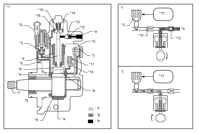
*1 Fuel Supply Pump Assembly *2 Fuel Quantity Control Valve *3 Flow Control Valve *4 Tappet Spring *5 Plunger *6 Tappet *7 Camshaft *8 Double Cam *9 Roller *10 Fuel Over Flow Valve *11 Fuel Over Flow Valve Spring *12 Check Ball Spring *13 Check Ball *14 Check Valve Spring *15 Check Valve *16 Valve Plate *17 ECM - - *a Camshaft Space *b Bearing Bush *c Fuel Inlet Port (from Fuel Pump Assembly) *d Fuel Return Port (to Fuel Tank Assembly) *e To Common Rail Assembly *f Return Fuel *g Fuel Feed *h High Pressure Fuel *i Plunger Moved from BDC to TDC *j Plunger Moved from TDC to BDC -
When the opening of the flow control valve in the fuel quantity control valve is small, the fuel flow area is kept small, which decreases the transferable fuel quantity.
-
Even when the plunger strokes fully, the flow volume continues to be small due to the small flow area.
-
Pumping will start when the fuel pressure has become higher than the total power of the common rail assembly pressure and the check ball spring force.
*a Small Flow Area - - -
When the opening of the flow control valve in the fuel quantity control valve is large, the fuel flow area is kept large, which increases the transferable fuel quantity.
-
If the plunger strokes fully, the flow volume will increase because the flow area is large.
-
Pumping will start when the fuel pressure has become higher than the total power of the common rail assembly pressure and the check ball spring force.
*a Large Flow Area - -
-
-
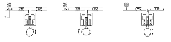
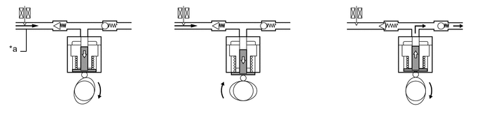
Injector Assembly
-
When electrical current is applied to the solenoid coil, it pulls the solenoid valve up.
-
The orifice of the control chamber opens, allowing the fuel to flow out.
-
The fuel pressure in the control chamber decreases.
-
Simultaneously, fuel flows from the orifice to the bottom of the piston and raises the piston up (to enhance response).
-
As a result, the piston raises the nozzle needle to inject fuel.
-
When the electrical current applied to the solenoid coil is stopped, the solenoid valve is pushed down and the orifice of the control chamber is closed.
-
The fuel pressure in the control chamber increases.
-
As a result, the piston and the nozzle needle are pushed down and fuel injection stops.
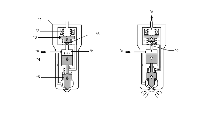
*1 Injector Assembly *2 Solenoid Coil *3 Solenoid Valve *4 Piston *5 Nozzle Needle *6 Check Ball *a Fuel (from Common Rail Assembly) *b Control Chamber *c Orifice *d Fuel (Return)
-
-