RELAY ON-VEHICLE INSPECTION
PROCEDURE
-
INSPECT INSTRUMENT PANEL JUNCTION BLOCK ASSEMBLY
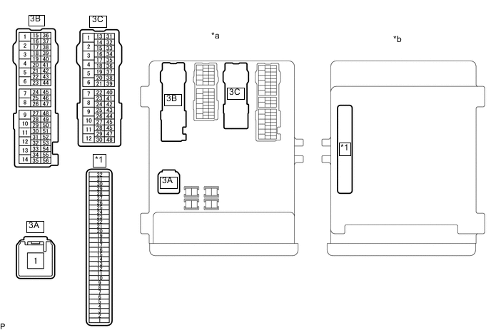
*1 Main Body ECU - - *a Component without harness connected
(Instrument Panel Junction Block Assembly)
*b Component without main body ECU connected
(Instrument Panel Junction Block Assembly)
Note
Before performing the relay inspections for the relays of the instrument panel junction block assembly, inspect the ECU-IG No. 1, ECU-IG No. 3 and S-HTR RH fuses.
-
Remove the instrument panel junction block assembly.
-
for LHD
-
for RHD
-
-
Remove the main body ECU from the instrument panel junction block assembly.
-
Inspect the IG1 No. 1 relay.
-
Measure the resistance according to the value(s) in the table below.
Standard Resistance Tester Connection Condition Specified Condition 3A-1 - 3B-50 Battery voltage is not applied to terminals 3C-43 and main body ECU-11 10 kΩ or higher 3A-1 - 3B-50 Battery voltage is applied to terminals 3C-43 and main body ECU-11 Below 1 Ω If the result is not as specified, replace the instrument panel junction block assembly.
-
-
Inspect the IG1 No. 2 relay.
-
Measure the resistance according to the value(s) in the table below.
Standard Resistance Tester Connection Condition Specified Condition 3A-1 - 3B-19 Battery voltage is not applied to terminals 3C-43 and main body ECU-11 10 kΩ or higher 3A-1 - 3B-19 Battery voltage is applied to terminals 3C-43 and main body ECU-11 Below 1 Ω If the result is not as specified, replace the instrument panel junction block assembly.
-
-
Inspect the IG1 No. 3 relay.
-
Measure the resistance according to the value(s) in the table below.
Standard Resistance Tester Connection Condition Specified Condition 3A-1 - 3C-3 Battery voltage is not applied to terminals 3C-43 and main body ECU-11 10 kΩ or higher 3A-1 - 3C-3 Battery voltage is applied to terminals 3C-43 and main body ECU-11 Below 1 Ω If the result is not as specified, replace the instrument panel junction block assembly.
-
-
Install the main body ECU to the instrument panel junction block assembly.
-
Install the instrument panel junction block assembly.
-
for LHD
-
for RHD
-
-
-
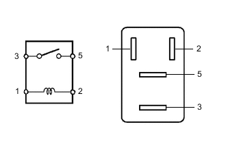
INSPECT IGNITION RELAY NO. 2 (IG2)
-
Measure the resistance according to the value(s) in the table below.
Standard Resistance Tester Connection Condition Specified Condition 3 - 5 Battery voltage not applied to terminals 1 and 2 10 kΩ or higher 3 - 5 Battery voltage applied to terminals 1 and 2 Below 1 Ω If the result is not as specified, replace the ignition relay No. 2.
-
-
INSPECT CIRCUIT OPENING RELAY (C/OPN)
-
Measure the resistance according to the value(s) in the table below.
Standard Resistance Tester Connection Condition Specified Condition 3 - 5 Battery voltage not applied to terminals 1 and 2 10 kΩ or higher 3 - 5 Battery voltage applied to terminals 1 and 2 Below 1 Ω If the result is not as specified, replace the circuit opening relay.
-
-
INSPECT EFI MAIN NO. 1 RELAY (EFI-MAIN NO. 1)
-
Measure the resistance according to the value(s) in the table below.
Standard Resistance Tester Connection Condition Specified Condition 3 - 5 Battery voltage not applied to terminals 1 and 2 10 kΩ or higher 3 - 5 Battery voltage applied to terminals 1 and 2 Below 1 Ω If the result is not as specified, replace the EFI main No. 1 relay.
-
-
INSPECT EFI MAIN NO. 2 RELAY (EFI-MAIN NO. 2)
-
Measure the resistance according to the value(s) in the table below.
Standard Resistance Tester Connection Condition Specified Condition 3 - 5 Battery voltage not applied to terminals 1 and 2 10 kΩ or higher 3 - 5 Battery voltage applied to terminals 1 and 2 Below 1 Ω If the result is not as specified, replace the EFI main No. 2 relay.
-