ENGINE UNIT REMOVAL

PROCEDURE
-
PRECAUTION
Note
-
After the engine has stopped, wait at least 1 minute before releasing the high pressure lines.
-
When working on the fuel circuit, protect the generator assembly against contamination. Cover the generator assembly with suitable materials. Failure to comply with this procedure may result in a generator assembly malfunction.
-
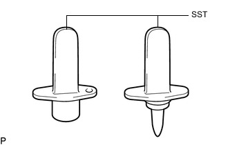
After disconnecting the pressure line, it is absolutely essential to seal the injector assemblies and the common rail assembly with SST.
SST PZ4TB-04941-79
-
-
REMOVE ENGINE COVER
-
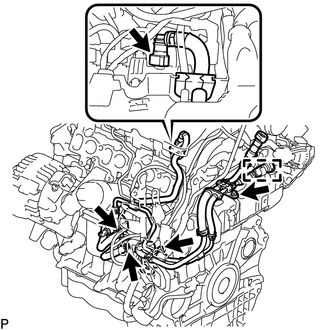
REMOVE ENGINE WIRE
-
Remove the engine wire from the engine assembly.
-
-
REMOVE V-RIBBED BELT
-
REMOVE COMPRESSOR ASSEMBLY WITH PULLEY (w/ Air Conditioning System)
-
REMOVE GENERATOR ASSEMBLY
-
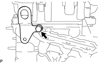
REMOVE IDLER PULLEY ASSEMBLY
-
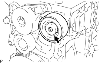
Using a T50 "TORX" socket wrench, loosen the bolt to remove the idler pulley assembly.
Tech Tips
The bolt cannot be removed from the idler pulley assembly.
-
-
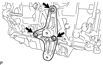
REMOVE ENGINE MOUNTING BRACKET
-
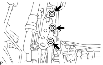
Using an E12 "TORX" socket wrench, remove the 3 bolts and engine mounting bracket.
-
Remove the 2 stud bolts from the engine mounting bracket.
-
-
REMOVE V-RIBBED BELT TENSIONER ASSEMBLY
-
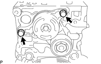
Remove the 2 bolts and V-ribbed belt tensioner assembly.
-
-
REMOVE DIESEL THROTTLE BODY ASSEMBLY
-
REMOVE ENGINE OIL LEVEL DIPSTICK GUIDE
-
DISCONNECT NO. 2 VACUUM HOSE ASSEMBLY
-
REMOVE NO. 2 VACUUM HOSE ASSEMBLY
-
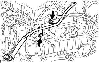
Remove the bolt, nut and No. 2 vacuum hose assembly from the No. 2 engine hanger.
-
-
REMOVE NO. 1 VACUUM PIPE
-
REMOVE INTAKE MANIFOLD
-
REMOVE FUEL FEED PIPE SUB-ASSEMBLY
-
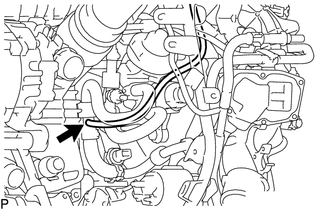
Disconnect the nozzle leakage pipe assembly from the fuel feed pipe sub-assembly.
-
Loosen the 2 clamps and disconnect the 2 fuel hoses from the fuel supply pump assembly.
-
Disconnect the fuel return tube from the common rail assembly.
-
Detach the fuel hose clamp.
-
Remove the 2 bolts and fuel feed pipe sub-assembly.
-
-
REMOVE NO. 1 EXHAUST MANIFOLD HEAT INSULATOR
-
REMOVE EXHAUST MANIFOLD CONVERTER SUB-ASSEMBLY
-
REMOVE TURBO OIL OUTLET PIPE
-
DISCONNECT NO. 1 TURBO OIL PIPE
-
REMOVE TURBOCHARGER SUB-ASSEMBLY
-
REMOVE EGR COOLER ASSEMBLY WITH EGR VALVE ASSEMBLY
-
REMOVE EXHAUST MANIFOLD
-
REMOVE NO. 1 TURBO OIL PIPE
-
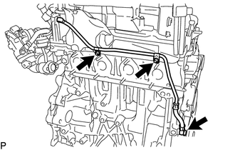
Remove the 2 nuts, union bolt, 2 gaskets and No. 1 turbo oil pipe.
-
-
REMOVE NO. 2 TURBO INSULATOR
-
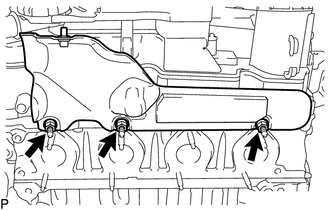
Remove the 3 bolts and No. 2 turbo insulator.
-
-
REMOVE TURBOCHARGER STAY
-
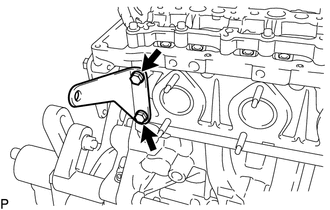
Remove the 2 bolts and turbocharger stay.
-
-
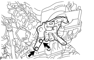
REMOVE EGR VALVE BRACKET
-
Remove the 2 bolts and EGR valve bracket from the cylinder head sub-assembly.
-
-
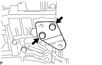
REMOVE NO. 2 ENGINE HANGER
-
Remove the 2 bolts and No. 2 engine hanger from the cylinder head sub-assembly.
-
-
REMOVE NO. 1 ENGINE HANGER
-
Remove the bolt and No. 1 engine hanger from the cylinder head sub-assembly.
-
-
REMOVE FUEL INLET PIPE SUB-ASSEMBLY
-
REMOVE INJECTION PIPE SUB-ASSEMBLY
-
REMOVE COMMON RAIL ASSEMBLY
-
REMOVE GLOW PLUG ASSEMBLY
-
REMOVE EGR BYPASS VALVE SWITCHING VALVE
-
REMOVE VACUUM CONTROL VALVE BRACKET
-
REMOVE DRIVE SHAFT BEARING BRACKET
-
Using a T50 "TORX" socket wrench, remove the 3 bolts and drive shaft bearing bracket.
-