SFI SYSTEM(w/ Canister Pump Module) ACIS Control Circuit
DESCRIPTION
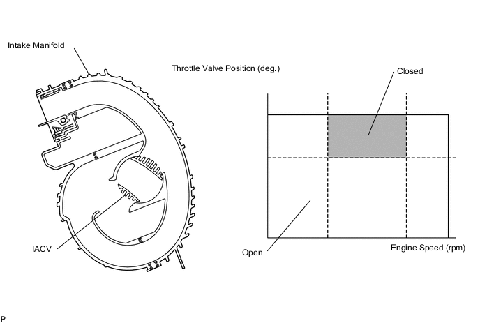
This circuit opens and closes the Intake Air Control Valve (IACV) according to the engine load in order to increase intake efficiency (ACIS: Acoustic Control Induction System).
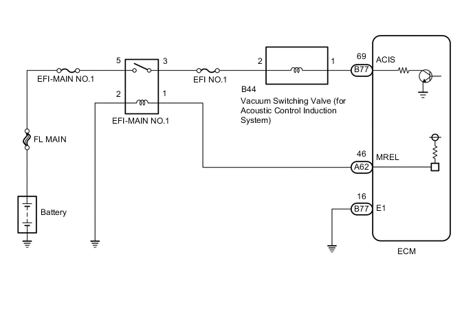
WIRING DIAGRAM
CAUTION / NOTICE / HINT
Note
Inspect the fuses for circuits related to this system before performing the following procedure.
PROCEDURE
-
PERFORM ACTIVE TEST USING GTS (OPERATE VACUUM SWITCHING VALVE FOR ACIS)
-
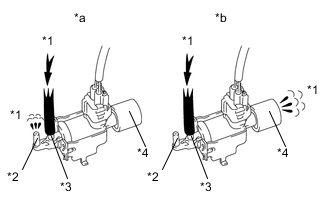
*1 Air *2 Port F *3 Port E *4 Air Filter *a Vacuum Switching Valve Assembly is ON *b Vacuum Switching Valve Assembly is OFF Disconnect the vacuum hose from port F of the vacuum switching valve assembly (for acoustic control induction system).
-
Connect the GTS to the DLC3.
-
Start the engine.
-
Enter the following menus: Powertrain / Engine and ECT / Active Test / Active the VSV for Intake Control.
Powertrain > Engine and ECT > Active TestTester Display Activate the VSV for Intake Control -
Operate the vacuum switching valve assembly for acoustic control induction system.
-
Check the vacuum switching valve assembly air flow when switching the vacuum switching valve assembly.
OK Test Condition Specified Condition Vacuum switching valve assembly is ON Air from port E flows out through port F Vacuum switching valve assembly is OFF Air from port E flows out through air filter Result Proceed to OK NG
NG 
INSPECT VACUUM SWITCHING VALVE ASSEMBLY (FOR ACIS) Click here
OK 
-
-
CHECK VACUUM HOSES (VACUUM SWITCHING VALVE (FOR ACIS) - INTAKE AIR CONTROL VALVE, INTAKE MANIFOLD)
-
Check the vacuum hoses.
Result Proceed to OK NG
NG 
REPAIR OR REPLACE VACUUM HOSES
OK
-
-
INSPECT INTAKE MANIFOLD (INTAKE AIR CONTROL VALVE)
-
Inspect the intake air control valve (for acoustic control induction system).
Result Proceed to OK NG
OK
PROCEED TO NEXT SUSPECTED AREA SHOWN IN PROBLEM SYMPTOMS TABLE Click here
NG
REPLACE INTAKE MANIFOLD Click here
-
-
INSPECT VACUUM SWITCHING VALVE ASSEMBLY (FOR ACIS)
-
Inspect the vacuum switching valve assembly (for acoustic control induction system).
Result Proceed to OK NG
NG
REPLACE VACUUM SWITCHING VALVE ASSEMBLY (FOR ACIS) Click here
OK
-
-
CHECK TERMINAL VOLTAGE (POWER SOURCE OF VACUUM SWITCHING VALVE ASSEMBLY)
-
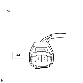
*a Front view of wire harness connector
(to Vacuum Switching Valve Assembly (for ACIS))
Disconnect the vacuum switching valve assembly connector.
-
Turn the ignition switch to ON.
-
Measure the voltage according to the value(s) in the table below.
Standard Voltage Tester Connection Switch Condition Specified Condition B44-2 - Body ground Ignition switch ON 11 to 14 V Result Proceed to OK NG
NG
CHECK HARNESS AND CONNECTOR (EFI-MAIN NO. 1 RELAY - VACUUM SWITCHING VALVE ASSEMBLY) Click here
OK
-
-
CHECK HARNESS AND CONNECTOR (VACUUM SWITCHING VALVE ASSEMBLY - ECM)
-
Disconnect the vacuum switching valve assembly connector.
-
Disconnect the ECM connector.
-
Measure the resistance according to the value(s) in the table below.
Standard Resistance Tester Connection Condition Specified Condition B44-1 - B77-69 (ACIS) Always Below 1 Ω B44-1 or B77-69 (ACIS) - Body ground Always 10 kΩ or higher Result Proceed to OK NG
OK
REPLACE ECM Click here
NG
REPAIR OR REPLACE HARNESS OR CONNECTOR
-
-
CHECK HARNESS AND CONNECTOR (EFI-MAIN NO. 1 RELAY - VACUUM SWITCHING VALVE ASSEMBLY)
-
Remove the EFI-MAIN No. 1 relay from the engine room relay block and junction block assembly.
-
Disconnect the vacuum switching valve assembly connector.
-
Measure the resistance according to the value(s) in the table below.
Standard Resistance Tester Connection Condition Specified Condition EFI-MAIN NO. 1 relay terminal 3 - B44-2 Always Below 1 Ω EFI-MAIN NO. 1 relay terminal 3 or B44-2 - Body ground Always 10 kΩ or higher Result Proceed to OK NG
OK
GO TO ECM POWER SOURCE CIRCUIT Click here
NG
REPAIR OR REPLACE HARNESS OR CONNECTOR
-