СИСТЕМА МЕХАНИЧЕСКОЙ ТРАНСМИССИИ КОНТАКТЫ ECM
-
ECM
Tech Tips
The standard voltage and resistance between each pair of ECM terminals is shown in the table below.
The appropriate conditions for checking each pair of terminals are also indicated. The result of checks should be compared with the standard voltage or resistance for that pair of terminals shown in the "Specified Condition" column.
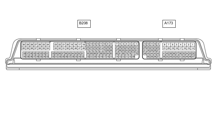
Use the illustration above as a reference for the ECM terminals.
Terminal No. (Symbol) Wiring Color Terminal Description Condition Specified Condition A173-1 (BATT) - B208-53 (E1) B - W-B Battery (for measuring battery voltage and for ECM memory) Always 11 to 14 V A173-2 (+B) - B208-53 (E1) B - W-B Power source of ECM Ignition switch ON 11 to 14 V A173-3 (+B2) - B208-53 (E1) B - W-B Power source of ECM Ignition switch ON 11 to 14 V A173-44 (SPD) - B208-53 (E1) V - W-B Vehicle speed signal from combination meter assembly signal Vehicle being driven Pulse generation A173-46 (MREL) - B208-53 (E1) L - W-B EFI MAIN relay Ignition switch ON 11 to 14 V B208-48 (+BM) - B208-53 (E1) B - W-B Power source of ECM Always 11 to 14 V B208-53 (E1) - Body ground W-B - Body ground Ground Always Below 1 Ω B208-76 (NE+) - B208-109 (NE-) R - Y Crankshaft position sensor signal Idling with warm engine Pulse generation B208-110 (VCNE) - B208-53 (E1) L - W-B Power source of crankshaft position sensor (specific voltage) Engine stopped, ignition switch ON 4.5 to 5.5 V