ВПУСКНОЙ КОЛЛЕКТОР УСТАНОВКА
PROCEDURE
-
INSTALL SWIRL CONTROL VALVE
-
Install the swirl control valve with the 3 bolts to the intake manifold.
Tech Tips
Refer to "SPECIFICATIONS - STANDARD BOLT" for the tightening torque.
-
Attach the rod to the swirl control valve.
-
-
INSTALL NO. 2 EGR PIPE
-
Install a new O-ring to the No. 2 EGR pipe.
-
Install the No. 2 EGR pipe to the intake manifold.
-
-
INSTALL EGR GAS TEMPERATURE SENSOR
-
INSTALL GLOW PLUG CONTROLLER ASSEMBLY
-
INSTALL TURBO PRESSURE SENSOR ASSEMBLY
-
INSTALL INTAKE MANIFOLD
-
Install a new gasket to the No. 2 EGR pipe.
Tech Tips
Make sure that the claw of the gasket faces the No. 2 EGR pipe.
-
Install 4 new gaskets to the intake manifold.
-
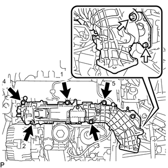

Bolt (A) 
Bolt (B) Temporarily install the intake manifold with the 7 bolts.
-
Tighten the 5 bolts (A) in the order shown in the illustration.
- Torque:
- 5.0 N*m { 51 kgf*cm, 44 in.*lbf }
-
Further tighten the 5 bolts (A) in the order shown in the illustration again.
- Torque:
- 10 N*m { 102 kgf*cm, 7 ft.*lbf }
-
Tighten the 2 bolts (B).
- Torque:
- 8.0 N*m { 82 kgf*cm, 71 in.*lbf }
-
-
INSTALL NO. 1 VACUUM PIPE
-
Install a new O-ring to the No. 1 vacuum pipe.
-
Using an E7 "TORX" socket wrench, install the No. 1 vacuum pipe to the cylinder block sub-assembly with the bolt.
- Torque:
- 8.0 N*m { 82 kgf*cm, 71 in.*lbf }
-
Connect the vacuum hose.
-
-
INSTALL NO. 2 VACUUM HOSE ASSEMBLY
-
Connect the No. 2 vacuum hose assembly to the No. 1 vacuum pipe.
-
Check that there is no damage or contamination in the connected part of the No. 1 vacuum pipe.
-
Line up the No. 1 vacuum pipe and No. 2 vacuum hose assembly connector and push them together until a "click" sound is heard. If the connection is tight, apply a small amount of clean engine oil to the tip of the No. 1 vacuum pipe.
-
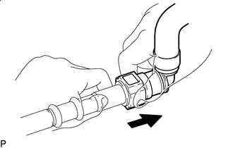
Pull After connecting the No. 1 vacuum pipe and No. 2 vacuum hose assembly connector, check that the No. 1 vacuum pipe and No. 2 vacuum hose assembly connector are securely connected by pulling on them.
-
-
-
INSTALL ENGINE OIL LEVEL DIPSTICK GUIDE
-
Install a new O-ring to the engine oil level dipstick guide.
-
Using a T25 "TORX" socket wrench, install the engine oil level dipstick guide with the bolt.
Tech Tips
Refer to "SPECIFICATIONS - STANDARD BOLT" for the tightening torque.
-
Attach the clamp and connect the fuel feed pipe sub-assembly to the engine oil level dipstick guide.
-
Install the engine oil level dipstick.
-
-
CONNECT ENGINE WIRE
-
Using a T25 "TORX" socket wrench, connect the engine wire and install the screw.
Tech Tips
Refer to "SPECIFICATIONS - STANDARD BOLT" for the tightening torque.
-
Attach the 2 clamps.
-
Connect the 2 glow plug controller assembly connectors.
-
Connect the turbo pressure sensor assembly connector.
-
Connect the camshaft position sensor connector.
-
Connect the generator assembly connector.
-
Connect the engine coolant temperature sensor connector.
-
Connect the fuel pressure sensor connector.
-
Connect the swirl control valve connector.
-
Attach the 6 clamps and connect the fuel quantity control valve connector.
-
Connect the EGR gas temperature sensor connector.
-
Attach the 3 clamps and connect the glow plug controller assembly harness connector.
-
-
INSTALL ENGINE COVER
-
INSTALL DIESEL THROTTLE BODY ASSEMBLY