PROCEDURE
- Click here
INSTALL FRONT EXHAUST PIPE ASSEMBLY
-
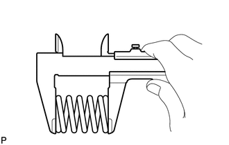
Using a vernier caliper, measure the free length of the compression springs.
Minimum 41.5 mm (1.63 in.) If the free length is less than the minimum, replace the compression spring.
-
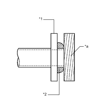
*1 No. 2 Exhaust Manifold Converter Sub-assembly *2 Gasket *a Wooden Block Using a plastic hammer and wooden block, tap in a new gasket until its surface is flush with the No. 2 exhaust manifold converter sub-assembly.
Note:
-
Be sure to install the gasket in the correct direction.
-
Do not reuse the gasket.
-
Do not damage the gasket.
-
Do not push in the gasket by using the exhaust pipe when connecting it.
-
-
Connect the front exhaust pipe assembly to the 2 exhaust pipe supports.
-
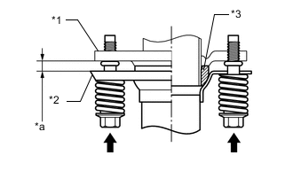
*1 No. 2 Exhaust Manifold Converter Sub-assembly *2 Front Exhaust Pipe Assembly *3 Gasket *a Space between flanges: 8.5 mm (0.335 in.) Install the front exhaust pipe assembly with the 2 bolts and 2 compression springs.
43 N*m 438 kgf*cm 32 ft.*lbf Tip:After installation, check that the space between the flanges of the No. 2 exhaust manifold converter sub-assembly and front exhaust pipe assembly are consistent front-to-rear and left-to-right.
-
- Click here
INSTALL FRONT NO. 3 ENGINE UNDER COVER (for Full Cover Type)
- Click here
INSTALL CENTER EXHAUST PIPE ASSEMBLY
-
Using a vernier caliper, measure the free length of the compression springs.
Minimum 38.5 mm (1.52 in.) If the free length is less than the minimum, replace the compression spring.
-
*1 Front Exhaust Pipe Assembly *2 Wooden Block *a Gasket Using a plastic hammer and wooden block, tap in a new gasket until its surface is flush with the front exhaust pipe assembly.
Note:
-
Be sure to install the gasket in the correct direction.
-
Do not reuse the gasket.
-
Do not damage the gasket.
-
Do not push in the gasket by using the exhaust pipes when connecting them.
-
-
Connect the center exhaust pipe assembly to the exhaust pipe support.
-
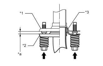
*1 Front Exhaust Pipe Assembly *2 Center Exhaust Pipe Assembly *3 Gasket *a Space between flanges: 6.5 mm (0.256 in.) Install the center exhaust pipe assembly with the 2 bolts and 2 compression springs.
43 N*m 438 kgf*cm 32 ft.*lbf Tip:After installation, check that the space between the flanges of the front exhaust pipe assembly and center exhaust pipe assembly are consistent front-to-rear and left-to-right.
-
- Click here
INSTALL FRONT CENTER FLOOR BRACE SUB-ASSEMBLY
-
Install the front center floor brace with the 4 bolts.
51 N*m 520 kgf*cm 38 ft.*lbf
-
- Click here
INSTALL TAIL EXHAUST PIPE ASSEMBLY
-
Install a new gasket to the center exhaust pipe assembly.
-
Connect the tail exhaust pipe assembly to the exhaust pipe support.
-
Install the tail exhaust pipe assembly with the 2 bolts.
43 N*m 438 kgf*cm 32 ft.*lbf
-