ДИФФЕРЕНЦИАЛЬНЫЙ ДАТЧИК ДАВЛЕНИЯ (для моделей без контроллера свечей накаливания) УСТАНОВКА

PROCEDURE
-
INSTALL DIFFERENTIAL PRESSURE SENSOR ASSEMBLY
-
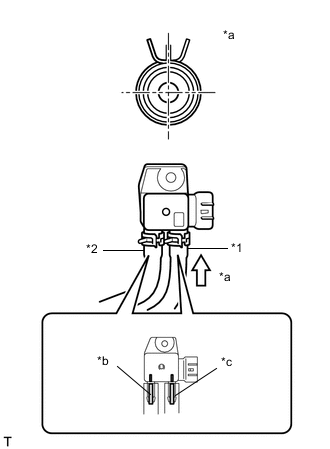
*1 Vacuum Transmitting Hose Assembly *2 No. 2 Vacuum Transmitting Hose Assembly *a View A *b Paint Mark (Yellow) *c Paint Mark (Pink) Connect the vacuum transmitting hose assembly and No. 2 vacuum transmitting hose assembly to the differential pressure sensor assembly and slide the 2 clips to secure them.
Note
Connect the vacuum transmitting hose assembly and No. 2 vacuum transmitting hose assembly so that the paint marks of the vacuum transmitting hose assembly and No. 2 vacuum transmitting hose assembly are as shown in the illustration.
-
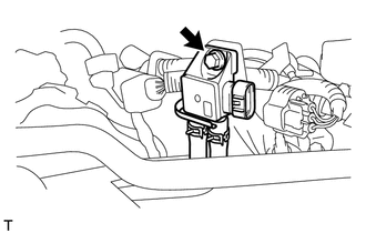
Install the differential pressure sensor assembly and bracket with the bolt .
- Torque:
- 5.0 N*m { 51 kgf*cm, 44 in.*lbf }
-
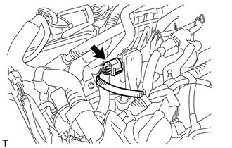
Connect the connector to the differential pressure sensor assembly.
-
-
INSTALL OUTER COWL TOP PANEL
-
INSTALL NO. 2 HEATER AIR DUCT SPLASH SHIELD SEAL (for LHD)
-
INSTALL NO. 2 HEATER AIR DUCT SPLASH SHIELD SEAL (for RHD)
-
INSTALL WATER GUARD PLATE LH (for LHD)
-
INSTALL WATER GUARD PLATE LH (for RHD)
-
INSTALL WINDSHIELD WIPER MOTOR AND LINK ASSEMBLY
-
INSTALL NO. 1 ENGINE COVER (w/ No. 1 Engine Cover)
-
LEARNING DIFFERENTIAL PRESSURE SENSOR ASSEMBLY
-
Start the engine and wait until the engine coolant temperature reaches 75°C (167°F) or more (A).
-
Turn the ignition switch off and wait for 30 seconds or more (B).
-
Repeat the above procedures (A) and (B) 3 times.
Tech Tips
-
Procedures (A) and (B) must be repeated 3 times to complete the differential pressure sensor learning process.
-
If the differential pressure sensor learning is incomplete, DTC P244A may be stored.
-
-