PROCEDURE
- Click here
INSTALL DIFFERENTIAL PRESSURE SENSOR ASSEMBLY
-
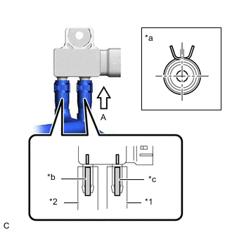
*1 No. 1 Vacuum Transmitting Hose Assembly *2 No. 2 Vacuum Transmitting Hose Assembly *a View A *b Marked Yellow *c Marked Pink Install the differential pressure sensor assembly to the sensor bracket with the bolt.
11 N*m 112 kgf*cm 8 ft.*lbf -
Connect the No. 2 vacuum transmitting hose assembly to the differential pressure sensor assembly and slide the clip to secure it.
-
Connect the No. 1 vacuum transmitting hose assembly to the differential pressure sensor assembly and slide the clip to secure it.
-
Engage the guide to install the No. 2 wire harness heat insulator to the differential pressure sensor assembly.
-
Return the No. 2 wire harness heat insulator and engage the snap fastener.
-
Engage the clamp to connect the engine wire to the sensor bracket.
-
Connect the differential pressure sensor assembly connector.
-
- Click here
INSTALL WIRE HARNESS CLAMP BRACKET
- Click here
INSTALL NO. 1 WIRE HARNESS HEAT INSULATOR
- Click here
INSTALL OUTER COWL TOP PANEL
-
for LHD:
-
for RHD:
-
- Click here
INSTALL NO. 2 HEATER AIR DUCT SPLASH SHIELD SEAL
-
for LHD:
-
for RHD:
-
- Click here
INSTALL WATER GUARD PLATE LH
-
for LHD:
-
for RHD:
-
- Click here
INSTALL WINDSHIELD WIPER MOTOR AND LINK ASSEMBLY
- Click here
INSTALL NO. 1 ENGINE COVER (w/ No. 1 Engine Cover)
- Click here
LEARNING DIFFERENTIAL PRESSURE SENSOR ASSEMBLY
-
Start the engine and wait until the engine coolant temperature reaches 75°C (167°F) or more. (A)
-
Turn the ignition switch off and wait for 30 seconds or more. (B)
-
Repeat the above procedures (A) and (B) 3 times.
Tip:
-
Procedures (A) and (B) must be repeated 3 times to complete the differential pressure sensor assembly learning process.
-
If the differential pressure sensor assembly learning is incomplete, DTC P244A may be stored.
-
-