КЛАПАН РОГ УСТАНОВКА
PROCEDURE
-
INSTALL EGR VALVE (ELECTRIC EGR CONTROL VALVE ASSEMBLY)
-
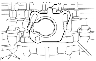
*a Protrusion Install a new gasket.
Note
Make sure the protrusion of the gasket is facing upward as shown in the illustration.
-
Install the EGR valve (electric EGR control valve assembly).
-
-
INSTALL NO. 2 EGR PIPE SUB-ASSEMBLY
-
Install a new gasket to the EGR valve (electric EGR control valve assembly).
-
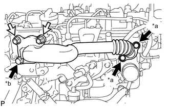
*a Bolt A *b Bolt B 
Bolt 
Nut Temporarily install the No. 2 EGR pipe sub-assembly with the 3 bolts and 2 nuts.
Bolt Length Item Specified Condition Bolt A 25 mm (0.984 in.) Bolt B 70 mm (2.76 in.) -
Tighten the 2 bolts (A) shown in the illustration.
- Torque:
- 24 N*m { 245 kgf*cm, 18 ft.*lbf }
-
Tighten the bolt (B) and 2 nuts shown in the illustration.
- Torque:
- 24 N*m { 245 kgf*cm, 18 ft.*lbf }
-
Connect the electric EGR control valve connector to the EGR valve (electric EGR control valve assembly).
-
-
CONNECT NO. 8 WATER BY-PASS HOSE
-
Connect the No. 8 water by-pass hose to the EGR valve (electric EGR control valve assembly) and slide the clip to secure it.
-
-
CONNECT NO. 7 WATER BY-PASS HOSE
-
Connect the No. 7 water by-pass hose to the EGR valve (electric EGR control valve assembly) and slide the clip to secure it.
-
-
INSTALL EGR VALVE BRACKET
-
Install the 2 EGR valve brackets with the 3 bolts.
- Torque:
- 24 N*m { 245 kgf*cm, 18 ft.*lbf }
-
Connect the 2 connectors and the 2 wire harness clamps.
-
-
ADD ENGINE COOLANT
-
INSPECT FOR COOLANT LEAK
-
INSTALL NO. 1 ENGINE COVER
-
PERFORM INITIALIZATION
-
When replacing the EGR valve (electric EGR control valve assembly), perform initialization.
-