ТОПЛИВНЫЙ БАК УСТАНОВКА
PROCEDURE
-
INSTALL FUEL RETURN TUBE SUB-ASSEMBLY
-
Engage the 2 claws to install the fuel return tube sub-assembly to the fuel tank assembly.
-
-
INSTALL FUEL TANK MAIN TUBE SUB-ASSEMBLY
-
w/o Combustion Type Power Heater:
-
Engage the 2 claws to install the fuel tank main tube sub-assembly to the fuel tank assembly.
-
-
w/ Combustion Type Power Heater:
-
Engage the 2 claws to install the fuel tank main tube sub-assembly and No. 2 fuel main tube sub-assembly to the fuel tank assembly.
-
-
-
INSTALL NO. 2 FUEL TANK CUSHION
-
Install a new No. 2 fuel tank cushion to the fuel tank assembly.
-
-
INSTALL NO. 1 FUEL TANK CUSHION
-
Install a new No. 1 fuel tank cushion to the fuel tank assembly.
-
-
INSTALL FUEL TANK ASSEMBLY
-
Set the fuel tank assembly on an engine lifter.
Note
Using height adjustment attachments and plate lift attachments, keep the fuel tank assembly horizontal.
-
Using the engine lifter, slowly raise the fuel tank assembly, and then install the fuel tank assembly with the 2 fuel tank bands with the 4 bolts.
Note
-
Be careful not to drop the fuel tank assembly.
-
When installing the fuel tank assembly, tilt it slightly to prevent it from interfering with the surrounding parts.
- Torque:
- 39.2 N*m { 400 kgf*cm, 29 ft.*lbf }
-
-
Connect the parking brake cable assembly with the 2 bolts.
- Torque:
- 6.0 N*m { 61 kgf*cm, 53 in.*lbf }
-
-
CONNECT FUEL TANK MAIN TUBE SUB-ASSEMBLY
Note
Check that there is no damage or foreign matter on the connecting parts of the fuel lines.
-
Connect the fuel tank main tube sub-assembly to the fuel pipe.
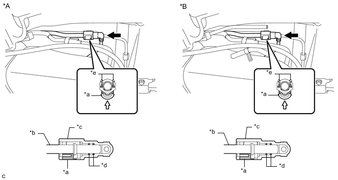
*A w/o Combustion Type Power Heater *B w/ Combustion Type Power Heater *a Retainer *b Fuel Pipe *c Fuel Tube Connector *d O-ring *e Claw - - 
Push 
Push in
-
Align the fuel tube connector with the fuel pipe, and push them together until the fuel tube connector makes a "click" sound. If it is difficult to push the fuel pipe into the fuel tube connector, apply a small amount of clean fuel to the tip of the fuel pipe and reinsert it.
-
Connect the fuel lines and push in the retainer to engage the 2 claws. Check that the fuel pipe and fuel tube connector are securely connected by pulling on them.
-
-
-
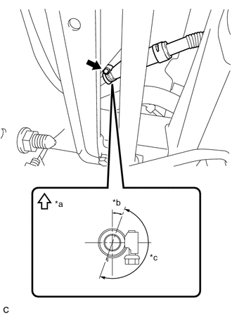
CONNECT NO. 2 FUEL MAIN TUBE SUB-ASSEMBLY (w/ Combustion Type Power Heater)
-
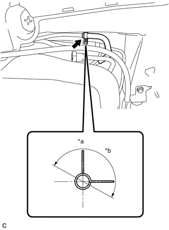
*a Up *b 180° Connect the No. 2 fuel main tube sub-assembly to the fuel pipe and slide the clip to secure it.
Tech Tips
Engage the clip within the area shown in the illustration.
-
-
CONNECT FUEL RETURN TUBE SUB-ASSEMBLY
Note
Check that there is no damage or foreign matter on the connecting parts of the fuel lines.
-
Connect the fuel return tube sub-assembly to the fuel pipe.
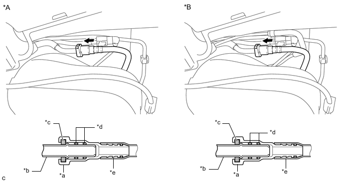
*A w/o Combustion Type Power Heater *B w/ Combustion Type Power Heater *a Fuel Tube Connector *b Fuel Pipe *c Retainer *d O-ring *e Nylon Tube - - Push - -
-
Align the fuel tube connector with the fuel pipe, and push them together until the fuel tube connector makes a "click" sound. If it is difficult to push the fuel pipe into the fuel tube connector, apply a small amount of clean fuel to the tip of the fuel pipe and reinsert it.
-
After connecting the fuel lines, check that the fuel pipe and fuel tube connector are securely connected by pulling on them.
-
-
-
CONNECT FUEL TANK TO FILLER PIPE HOSE
-
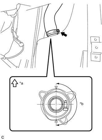
*a Up *b 180° (Clamp Bolt Area) Connect the fuel tank to filler pipe hose to the fuel tank assembly and tighten the clamp to secure it.
Tech Tips
Make sure the bolt of the clamp is positioned within the area shown in the illustration.
-
-
CONNECT FUEL TANK VENT HOSE
-
*a Up *b 20° *c 180° (Clamp Bolt Area) Connect the fuel tank vent hose to the fuel tank filler pipe sub-assembly and tighten the clamp to secure it.
Tech Tips
Make sure the bolt of the clamp is positioned within the area shown in the illustration.
-
-
INSTALL NO. 1 FUEL TANK PROTECTOR
-
Install the No. 1 fuel tank protector to the fuel tank assembly with the 3 bolts.
- Torque:
- 5.5 N*m { 56 kgf*cm, 49 in.*lbf }
-
-
INSTALL TAIL EXHAUST PIPE ASSEMBLY
-
INSTALL REAR FLOOR SIDE MEMBER COVER LH
-
INSTALL REAR FLOOR SIDE MEMBER COVER RH
-
INSTALL FUEL SUCTION TUBE WITH PUMP AND GAUGE ASSEMBLY
-
ADD FUEL