ТОПЛИВНЫЙ НАСОС СНЯТИЕ

PROCEDURE
-
REMOVE REAR SEAT CUSHION ASSEMBLY
-
REMOVE REAR FLOOR SERVICE HOLE COVER
-
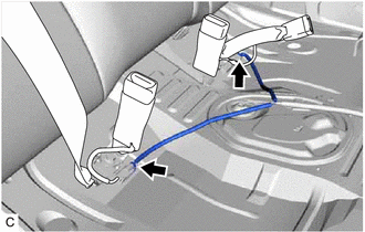
Disconnect the 2 connectors.
-
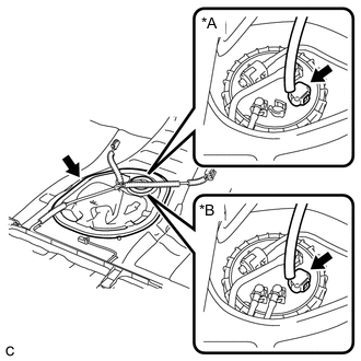
*A w/o Combustion Type Power Heater *B w/ Combustion Type Power Heater Remove the rear floor service hole cover and butyl tape.
-
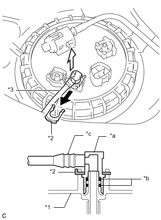
Disconnect the fuel pump connector.
-
-
DISCONNECT FUEL RETURN TUBE SUB-ASSEMBLY
-
Remove the tube joint clip, and pull off the fuel tube joint of the fuel return tube sub-assembly.
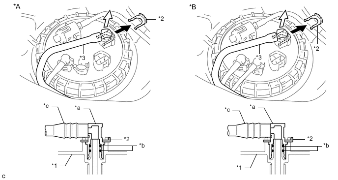
*A w/o Combustion Type Power Heater *B w/ Combustion Type Power Heater *1 Fuel Suction Plate Sub-assembly *2 Tube Joint Clip *3 Fuel Tank Return Tube Sub-assembly - - *a Fuel Tube Joint *b O-ring *c Nylon Tube - - 
Pull off 
Pull off Note
-
Remove any foreign matter on the fuel tube joint before performing this work.
-
Do not scratch or allow any foreign matter to get on the parts when disconnecting them as the fuel tube connector has O-rings that seal the pipe (fuel pipe).
-
Be sure to disconnect the fuel tube joint by hand.
-
Do not bend, twist, pinch or kink the nylon tube.
-
Protect the disconnected part by covering it with a plastic bag after disconnecting the fuel tube joint.
-
If the fuel tube joint and fuel suction plate sub-assembly are stuck, push and pull to release them.
-
-
-
DISCONNECT FUEL TANK MAIN TUBE SUB-ASSEMBLY
-
Remove the tube joint clip, and pull off the fuel tube joint of the fuel tank main tube sub-assembly.
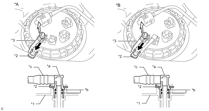
*A w/o Combustion Type Power Heater *B w/ Combustion Type Power Heater *1 Fuel Suction Plate Sub-assembly *2 Tube Joint Clip *3 Fuel Tank Main Tube Sub-assembly - - *a Fuel Tube Joint *b O-ring *c Nylon Tube - - Pull off Pull off Note
-
Remove any foreign matter on the fuel tube joint before performing this work.
-
Do not scratch or allow any foreign matter to get on the parts when disconnecting them as the fuel tube connector has O-rings that seal the pipe (fuel pipe).
-
Be sure to disconnect the fuel tube joint by hand.
-
Do not bend, twist, pinch or kink the nylon tube.
-
Protect the disconnected part by covering it with a plastic bag after disconnecting the fuel tube joint.
-
If the fuel tube joint and fuel suction plate sub-assembly are stuck, push and pull to release them.
-
-
-
DISCONNECT NO. 2 FUEL MAIN TUBE SUB-ASSEMBLY (w/ Combustion Type Power Heater)
-
*1 Fuel Suction Plate Sub-assembly *2 Tube Joint Clip *3 No. 2 Fuel Main Tube Sub-assembly *a Fuel Tube Joint *b O-ring *c Nylon Tube Pull off Pull off Remove the tube joint clip, and pull off the fuel tube joint of the No. 2 fuel main tube sub-assembly.
Note
-
Remove any foreign matter on the fuel tube joint before performing this work.
-
Do not scratch or allow any foreign matter to get on the parts when disconnecting them as the fuel tube connector has O-rings that seal the pipe (fuel pipe).
-
Be sure to disconnect the fuel tube joint by hand.
-
Do not bend, twist, pinch or kink the nylon tube.
-
Protect the disconnected part by covering it with a plastic bag after disconnecting the fuel tube joint.
-
If the fuel tube joint and fuel suction plate sub-assembly are stuck, push and pull to release them.
-
-
-
REMOVE TANK SUCTION TUBE SUPPORT
-
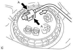
Pinch Pull Pinch the tabs (A) from both sides of the fuel tank evaporation vent tube sub-assembly.
-
Pull the fuel tank evaporation vent tube sub-assembly in the direction indicated by the arrow in the illustration.
-
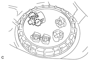
Disengage the 2 claws and remove the tank suction tube support.
-
-
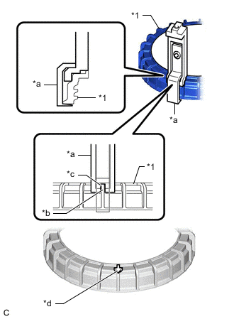
REMOVE FUEL PUMP GAUGE RETAINER
Note
Before performing these procedures, first cover the connector and fuel tube joint of the fuel suction tube with pump and gauge assembly with vinyl tape and then clean any dirt and foreign matter in order to prevent contamination of the fuel system.
-
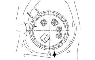
*a Paint Mark Front Place paint marks on the fuel suction tube with pump and gauge assembly and vehicle body as shown in the illustration.
Note
-
The fuel suction tube with pump and gauge assembly has 2 protrusions that engage with 2 notches on the fuel tank assembly to ensure correct alignment and to prevent the fuel suction tube with pump and gauge assembly from turning during installation and removal of the fuel pump gauge retainer.
-
If the fuel pump gauge retainer is turned with the fuel suction tube with pump and gauge assembly misaligned, the fuel suction tube with pump and gauge assembly will turn with the fuel pump gauge retainer and may be damaged.
-
The paint marks are used to ensure that the fuel suction tube with pump and gauge assembly does not turn with the fuel pump gauge retainer.
-
-
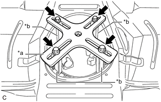
Install SST to the fuel pump gauge retainer.
-
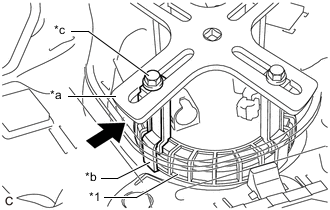
*1 Fuel Pump Gauge Retainer *a SST (Claw Set) *b Protrusion *c Notch *d Do not install SST (Claw Set) Set 4 SST (claw set) to the fuel pump gauge retainer.
- SST
- 09808-14031 ( 09808-01080, 09808-01090, 09808-01100 )
Note
-
Align the notch of SST (claw set) with the protrusion of the fuel pump gauge retainer.
-
Do not install SST (claw set) to the start of threads location of the fuel pump gauge retainer.
-
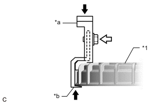
*1 Fuel Pump Gauge Retainer *a SST (Claw Set) *b Hook Push SST (Bolt) Push SST (claw set) against the fuel pump gauge retainer and tighten SST (bolt).
-
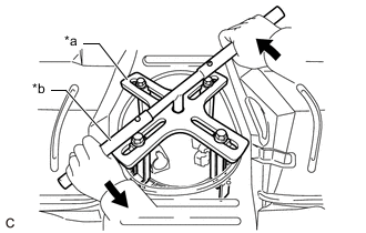
*a SST (Plate) *b SST (Claw Set) SST (Bolt) Temporarily install SST (plate) to SST (claw set) with 4 SST (bolt).
- SST
- 09808-14031 ( 09808-01030, 09808-01090 )
-
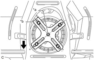
*a Center Point of Fuel Pump Gauge Retainer *b SST (Plate) Front Adjust the position of SST (claw set) so that the hole in SST (plate) for installing SST (handle) is in the center of the fuel pump gauge retainer.
-
*1 Fuel Pump Gauge Retainer *a SST (Plate) *b SST (Claw Set) *c SST (Bolt) Press Press SST (claw set) against the rib of the fuel pump gauge retainer and tighten SST (bolt).
-
Install SST (handle) to SST (plate).
- SST
- 09808-14031 ( 09808-01010, 09808-01020 )
-
-
*a SST (Plate) *b SST (Handle) Loosen Slowly loosen the fuel pump gauge retainer by approximately 90°.
Note
Do not spin SST too fast or use an impact wrench as this may result in damage to components.
-
While one person loosens the fuel pump gauge retainer, have another person press down the rising fuel suction tube with pump and gauge assembly, securely insert the protrusion of the fuel suction tube with pump and gauge assembly into the groove of the fuel tank assembly, and then remove the fuel pump gauge retainer while making sure that the fuel suction tube with pump and gauge assembly is properly aligned.
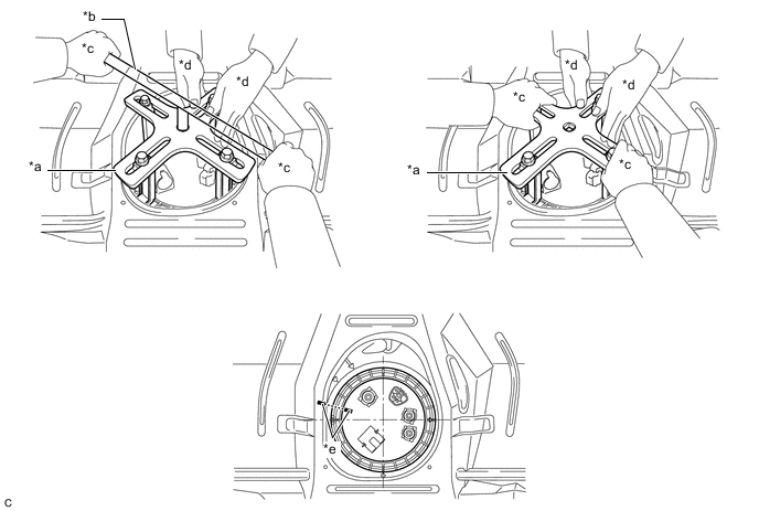
*a SST (Plate) *b SST (Handle) *c One Person in Charge of Loosening *d One Person in Charge of Pressing Down *e Paint Mark - - Note
-
The fuel suction tube with pump and gauge assembly is pressed against the underside of the fuel tank assembly by a spring, and the constant upward pressure applied by this spring causes the fuel suction tube with pump and gauge assembly to rise up.
-
If the fuel pump gauge retainer is turned while the fuel suction tube with pump and gauge assembly and fuel tank assembly are not correctly aligned, the fuel suction tube with pump and gauge assembly will move with the fuel pump gauge retainer, and the fuel suction tube with pump and gauge assembly and fuel tank assembly may both be damaged.
-
Do not turn the fuel pump gauge retainer if the paint marks become misaligned.
-
-
-
REMOVE FUEL SUCTION TUBE WITH PUMP AND GAUGE ASSEMBLY
-
Remove the fuel suction tube with pump and gauge assembly from the fuel tank assembly.
Note
Be careful not to bend the arm of the fuel sender gauge assembly.
-
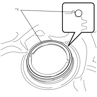
*1 Fuel Suction Tube Set Gasket Remove the fuel suction tube set gasket from the fuel tank assembly.
-
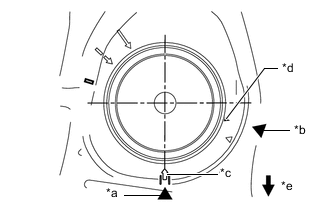
*a Copy of Fully Tightened Mark *b Copy of Start of Threads Mark *c Fully Tightened Mark on Fuel Tank Assembly *d Start of Threads Mark on Fuel Tank Assembly *e Front Copy the fully tightened mark and start of threads mark of the fuel tank assembly.
-
Copy the start of threads mark and fully tightened mark from the fuel tank assembly to the vehicle body in order to record their locations.
-
-
-
REMOVE FUEL SENDER GAUGE ASSEMBLY