ТОПЛИВНАЯ СИСТЕМА МЕРЫ ПРЕДОСТОРОЖНОСТИ
-
IGNITION SWITCH EXPRESSIONS
-
The type of ignition switch used on this model differs depending on the specifications of the vehicle. The expressions listed in the table below are used in this section.
Expression Ignition Switch (Position) Engine Switch (Condition) Ignition Switch off LOCK Off (Lock) Ignition Switch ACC ACC On (ACC) Ignition Switch ON ON On (IG) Engine Start START On (Start)
-
-
FUEL LINE
-
When disconnecting the fuel line, fuel will spray. So perform following procedure.
-
Disconnect the fuel tube.
-
Release the pressure remaining in the fuel tank main tube sub-assembly.
-
Cover the disconnected fuel tank main tube sub-assembly (fuel tube joint and fuel tube connector) with a plastic bag to prevent damage and entry of foreign matter.
-
-
Quick Type A:
Perform the following procedure when disconnecting a fuel tube connector.
Note
Remove any foreign matter on the fuel tube connector and fuel pipe before performing this work.
-
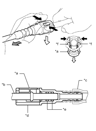
*a Retainer *b Fuel Pipe *c Nylon Tube *d Fuel Tube Connector *e O-ring *f Claw 
Push 
Pull out 
Pull off Disengage the 2 claws of the retainer. Pull out the retainer and disconnect the fuel tube connector from the fuel pipe.
Note
Be sure to disconnect the fuel tube connector by hand.
-
If the fuel tube connector and fuel pipe are stuck, push and pull the fuel tube connector to release it. Pull the fuel tube connector off of the fuel pipe carefully.
Note
-
Be sure to disconnect the fuel tube connector by hand.
-
Do not scratch or allow any foreign matter to get on the parts when disconnecting them as the fuel tube connector has O-rings that seal the pipe (fuel pipe).
-
Do not bend, twist, pinch or kink the nylon tube.
-
-
Check that there is no foreign matter on the sealing surfaces of the disconnected fuel lines. Clean them if necessary.
-
Cover the disconnected fuel pipe and fuel tube connector with plastic bags to prevent damage and contamination.
-
-
Quick Type A:
Perform the following procedure when connecting a fuel tube connector.
Note
Check that there is no damage or foreign matter on the connecting parts of the fuel lines.
-
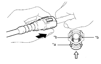
*a Retainer *b Claw Push Push in Align the fuel tube connector with the fuel pipe, and push them together until the fuel tube connector makes a "click" sound. If it is difficult to push the fuel pipe into the fuel tube connector, apply a small amount of clean fuel to the tip of the fuel pipe and reinsert it.
-
Connect the fuel lines and push in the retainer to engage the 2 claws. Check that the fuel pipe and fuel tube connector are securely connected by pulling on them.
-
Inspect for fuel leaks.
-
-
Quick Type B:
Perform the following procedure when disconnecting a fuel tube connector.
Note
Remove any foreign matter on the fuel tube connector and fuel pipe before performing this work.
-
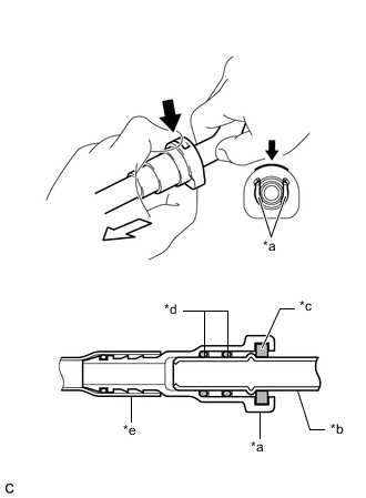
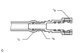
*a Fuel Tube Connector *b Fuel Pipe *c Retainer *d O-ring *e Nylon Tube Push Pull off Push the retainer of the fuel tube connector, and then pull the fuel tube connector off of the fuel pipe.
Note
Be sure to disconnect the fuel tube connector by hand.
-
If the fuel tube connector and fuel pipe are stuck, push and pull the fuel tube connector to release it. Pull the fuel tube connector off of the fuel pipe carefully.
Note
-
Be sure to disconnect the fuel tube connector by hand.
-
Do not scratch or allow any foreign matter to get on the parts when disconnecting them as the fuel tube connector has O-rings that seal the pipe (fuel pipe).
-
Do not bend, twist, pinch or kink the nylon tube.
-
-
Check that there is no foreign matter on the sealing surfaces of the disconnected fuel lines. Clean them if necessary.
-
Cover the disconnected fuel pipe and fuel tube connector with plastic bags to prevent damage and contamination.
-
-
Quick Type B:
Perform the following procedure when connecting a fuel tube connector.
Note
Check that there is no damage or foreign matter on the connecting parts of the fuel lines.
-
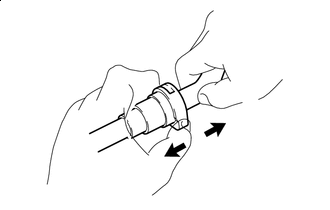
Pull Align the fuel tube connector with the fuel pipe, and push them together until the fuel tube connector makes a "click" sound. If it is difficult to push the fuel pipe into the fuel tube connector, apply a small amount of clean fuel to the tip of the fuel pipe and reinsert it.
-
After connecting the fuel lines, check that the fuel pipe and fuel tube connector are securely connected by pulling on them.
-
Inspect for fuel leaks.
-
-
*a Fuel Tube Connector *b Nylon Tube *c Ethylene Propylene Diene Monomer (EPDM) Rubber Protector Observe the following precautions when handling a nylon tube:
Note
-
Do not twist the fuel tube connector of the nylon tube or fuel tube connector when connecting it.
-
Do not remove the Ethylene Propylene Diene Monomer (EPDM) rubber protector on the outside of the nylon tube.
-
Do not bend, twist, pinch or kink the nylon tube.
-
-
-
CHECK FOR FUEL LEAKAGE
-
Check that there is no fuel leakage after performing maintenance on the fuel system.
-
-
BLEED AIR FROM FUEL SYSTEM
-
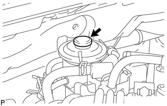
Using the hand pump mounted on the fuel filter cap, bleed the air from the fuel system. Continue pumping until the pump resistance increases.
Note
-
Hand pump pumping speed: Maximum 2 strokes/second.
-
Operate the hand pump in full strokes during pumping.
-
When the fuel pressure at the supply pump inlet port reaches a saturated pressure, the hand pump resistance increases.
-
If pumping is interrupted during the air bleeding process, fuel in the fuel line may return to the fuel tank assembly. Continue pumping until the hand pump resistance increases.
-
If the hand pump resistance does not increase despite consecutively pumping 200 times or more, there may be a fuel leak between the fuel tank assembly and fuel filter assembly, the hand pump may be malfunctioning, or the vehicle may have run out of fuel.
-
If air bleeding using the hand pump is incomplete, the common rail pressure does not rise to the pressure range necessary for normal use, and the engine cannot be started.
-
-
Start the engine.
Note
-
Even if air bleeding using the hand pump has been completed, the starter may need to be cranked for 10 seconds or more to start the engine.
-
Do not crank the engine continuously for more than 20 seconds. The battery may be discharged.
-
Use a fully-charged battery.
-
When the engine can be started, proceed to the next step.
-
If the engine cannot be started, bleed the air again using the hand pump until the hand pump resistance increases (refer to the procedures above). Then start the engine.
-
-
Turn the ignition switch off.
-
Connect the GTS to the DLC3.
-
Turn the ignition switch to ON.
-
Turn the GTS on.
-
Clear DTCs.
-
Start the engine. [*1]
-
Enter the following menus: Powertrain / Engine and ECT / Active Test / Test the Fuel Leak. [*2]
Powertrain > Engine and ECT > Active TestTester Display Test the Fuel Leak -
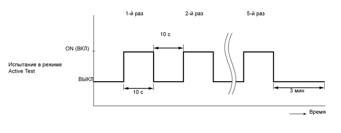
Perform the following test 5 times at on/off intervals of 10 seconds: Active Test / Test the Fuel Leak. [*3]
-
Allow the engine to idle for 3 minutes or more.
Tech Tips
When the Active Test "Test the Fuel Leak" is used to change the pump control mode, the actual fuel pressure inside the common rail drops below the target fuel pressure when the Active Test is off, but this is normal and does not indicate a pump malfunction.
-
Check for DTCs.
-
When no DTCs are output, the air bleeding is completed.
-
If any DTCs are output, proceed to the next step.
Tech Tips
DTC P1603 (Engine Stall History), DTC P1604 (Startability Malfunction) and DTC P1605 (Rough Idling) may be stored.
-
-
Clear the DTCs.
-
Repeat steps [*1] to [*3].
-
Check for DTCs.
-