НАГНЕТАЮЩИЙ ТОПЛИВНЫЙ НАСОС СНЯТИЕ
CAUTION / NOTICE / HINT
Note
-
When replacing the injector assemblies (including exchanging the injector assemblies between the cylinders), common rail assembly, intake manifold or cylinder head, it is necessary to replace the injection pipes with new ones.
-
When replacing the supply pump assembly, common rail assembly, intake manifold or cylinder head, it is necessary to replace the fuel inlet pipe with a new one.
Tech Tips
After replacing the supply pump assembly, perform the "SUPPLY PUMP INITIALIZATION PROCEDURE" function using the GTS.
PROCEDURE
-
PRECAUTION
Note
After turning the ignition switch off, waiting time may be required before disconnecting the cable from the negative (-) battery terminal. Therefore, make sure to read the disconnecting the cable from the negative (-) battery terminal notice before proceeding with work.
-
DISCONNECT CABLE FROM NEGATIVE BATTERY TERMINAL
Note
When disconnecting the cable, some systems need to be initialized after the cable is reconnected.
-
REMOVE NO. 1 ENGINE COVER
-
REMOVE AIR CLEANER CAP SUB-ASSEMBLY
-
REMOVE AIR CLEANER CASE SUB-ASSEMBLY
-
REMOVE NO. 3 FUEL HOSE
-
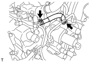
Slide the 2 clips and remove the No. 3 fuel hose.
-
-
REMOVE NO. 1 FUEL HOSE
-
Slide the 2 clips and remove the No. 1 fuel hose.
-
-
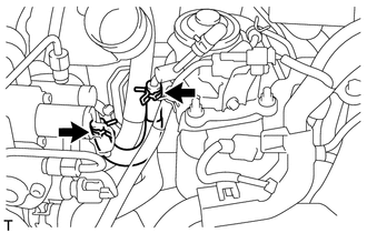
REMOVE FUEL INLET PIPE SUB-ASSEMBLY
Note
After removing the fuel inlet pipe sub-assembly, cover the common rail assembly and supply pump assembly to prevent contamination.
-
Remove the nut and injection pipe clamp.
-
Using a 14 mm union nut wrench, loosen the 2 nuts to remove the fuel inlet pipe sub-assembly.
-
-
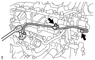
REMOVE FUEL HOSE PROTECTOR
-
REMOVE FUEL TUBE SUB-ASSEMBLY
-
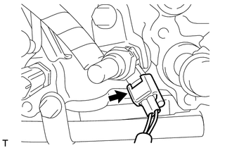
Disconnect the exhaust fuel addition injector assembly connector.
-
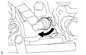
Turn the retainer as shown in the illustration.
Note
-
Check that there are no scratches or foreign matter around the connecting parts of the fuel tube connector and exhaust fuel addition injector assembly before performing this work.
-
Do not allow any scratches or foreign matter to get on the parts when disconnecting them as the fuel tube connector has an O-ring that seals the exhaust fuel addition injector assembly.
-
Only disconnect the fuel tube connector by hand.
-
Protect the disconnected part by covering it with a plastic bag after disconnecting the fuel tube connector.
-
If the fuel tube connector and exhaust fuel addition injector assembly are stuck, push and pull to release them.
-
-
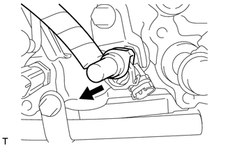
Disconnect the fuel tube sub-assembly from the exhaust fuel addition injector assembly.
-
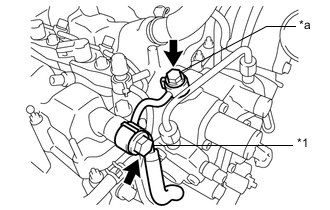
*1 Check Valve *a Union Bolt Remove the check valve and gasket.
-
Remove the union bolt and fuel tube sub-assembly with the gasket.
-
-
REMOVE SUPPLY PUMP ASSEMBLY
-
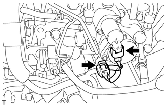
Disconnect the fuel temperature sensor connector.
-
Disconnect the suction control valve assembly connector.
-
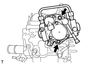
Remove the 2 bolts, supply pump assembly and supply pump drive coupling.
-
Remove the O-ring from the supply pump assembly.
-