ДВИГАТЕЛЬ В СБОРЕ СНЯТИЕ
CAUTION / NOTICE / HINT
CAUTION:
The engine assembly with transaxle is very heavy. Be sure to follow the procedure described in the repair manual, or the engine lifter may suddenly drop.
PROCEDURE
-
PRECAUTION
Note
After turning the engine switch off, waiting time may be required before disconnecting the cable from the negative (-) battery terminal. Therefore, make sure to read the disconnecting the cable from the negative (-) battery terminal notices before proceeding with work.
-
RECOVER REFRIGERANT FROM REFRIGERATION SYSTEM (w/ Air Conditioning System)
-
DISCHARGE FUEL SYSTEM PRESSURE
-
ALIGN FRONT WHEELS FACING STRAIGHT AHEAD
-
DISCONNECT CABLE FROM NEGATIVE BATTERY TERMINAL
Note
When disconnecting the cable, some systems need to be initialized after the cable is reconnected.
-
REMOVE FRONT WHEELS
-
REMOVE FRONT LOWER BUMPER ABSORBER
-
Remove the 8 bolts, 4 screws and front lower bumper absorber.
-
-
REMOVE NO. 1 ENGINE UNDER COVER
-
for Full Cover Type:
-
Remove the 2 bolts, 11 clips and No. 1 engine under cover.
-
-
for Half Cover Type:
-
Remove the 2 bolts, 7 clips and No. 1 engine under cover.
-
-
-
REMOVE CENTER NO. 4 ENGINE UNDER COVER (w/ Cover)
-
for Full Cover Type:
-
Remove the 2 clips and center No. 4 engine under cover.
-
-
for Half Cover Type:
-
Remove the 5 clips and center No. 4 engine under cover.
-
-
-
REMOVE REAR ENGINE UNDER COVER LH
-
Remove the 5 clips and rear engine under cover LH.
-
-
REMOVE REAR ENGINE UNDER COVER RH
-
Remove the 5 clips and rear engine under cover RH.
-
-
DRAIN ENGINE OIL
-
DRAIN ENGINE COOLANT
-
DRAIN COOLANT (for Intercooler)
-
DRAIN CONTINUOUSLY VARIABLE TRANSAXLE FLUID (for CVT)
-
DRAIN MANUAL TRANSAXLE OIL (for Manual Transaxle)
-
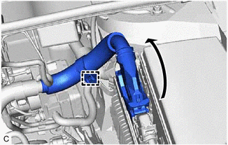
REMOVE NO. 1 ENGINE COVER SUB-ASSEMBLY
-
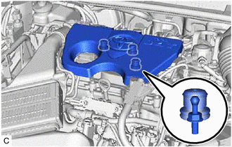
Hold the rear of the No. 1 engine cover sub-assembly and raise it to disengage the 2 rear retainers.
-
Raise the No. 1 engine cover sub-assembly to disengage the front retainer, and remove the No. 1 engine cover sub-assembly.
Note
Attempting to disengage both front and rear retainers at the same time may cause the No. 1 engine cover sub-assembly to break.
-
-
REMOVE AIR CLEANER CAP WITH AIR CLEANER HOSE
-
REMOVE AIR CLEANER CASE SUB-ASSEMBLY
-
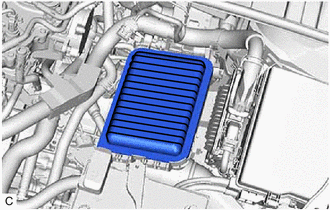
Remove the air cleaner filter element sub-assembly from the air cleaner case sub-assembly.
-
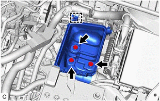
Disconnect the wire harness clamp from the air cleaner case sub-assembly.
-
Remove the 3 bolts and air cleaner case sub-assembly from the engine mounting insulator LH.
-
-
DISCONNECT NO. 1 RADIATOR HOSE
-
DISCONNECT NO. 2 RADIATOR HOSE
-
DISCONNECT NO. 1 TURBO WATER HOSE
-
DISCONNECT NO. 4 TURBO WATER HOSE
-
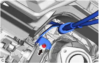
DISCONNECT TRANSMISSION CONTROL CABLE ASSEMBLY (for CVT)
-
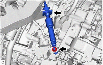
Remove the nut and disconnect the transmission control cable assembly from the control shaft lever.
-
Remove the clip and disconnect the transmission control cable assembly from the No. 1 transmission control cable bracket.
-
Remove the bolt and disconnect the transmission control cable assembly from the rear engine mounting insulator.
-
-
DISCONNECT TRANSMISSION CONTROL CABLE ASSEMBLY (for Manual Transaxle)
-
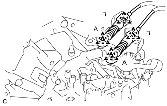
Remove the 2 clips (A) and disconnect the transmission control cable assembly from the manual transaxle assembly.
-
Remove the 2 clips (B) and disconnect the transmission control cable assembly from the control cable bracket assembly.
-
Remove the bolt and disconnect the transmission control cable assembly from the rear engine mounting insulator.
-
-
DISCONNECT UNION TO CONNECTOR TUBE HOSE
-
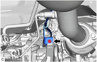
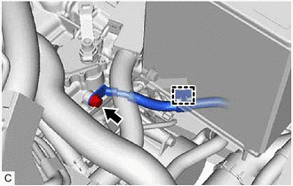
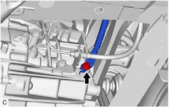
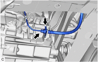
DISCONNECT FUEL VAPOR FEED HOSE
-
Slide the clip and disconnect the fuel vapor feed hose from the fuel vapor feed pipe.
-
-
DISCONNECT HEATER WATER OUTLET HOSE A
-
DISCONNECT HEATER WATER INLET HOSE A
-
DISCONNECT FUEL TUBE SUB-ASSEMBLY
-
DISCONNECT DISCHARGE HOSE SUB-ASSEMBLY (w/ Air Conditioning System)
-
DISCONNECT SUCTION HOSE SUB-ASSEMBLY (w/ Air Conditioning System)
-
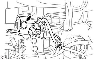
DISCONNECT WIRE HARNESS
-
Disengage the wire harness clamp.
-
Raise the lever while pushing the lock on the lever, and disconnect the ECM connector.
Note
After disconnecting the ECM connector, make sure that dirt, water or other foreign matter does not contact the connecting parts of the ECM connector.
-
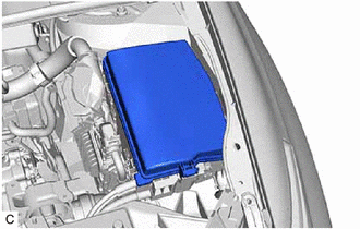
Remove the No. 1 relay block cover from the engine room relay block assembly.
-
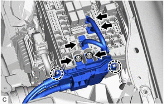
Disconnect the 3 connectors from the engine room relay block assembly.
-
Remove the 2 nuts from the engine room relay block assembly.
-
Disengage the 2 claws and disconnect the wire harness from the engine room relay block assembly.
-
for CVT:
-
Disengage the clamp from the wire harness clamp bracket.
-
Remove the bolt and disconnect the No. 3 engine wire from the continuously variable transaxle assembly.
-
-
for Manual Transaxle:
-
Remove the bolt and disconnect the No. 3 engine wire from the manual transaxle assembly.
-
-
Loosen the nut and disconnect the cable from the positive (+) battery terminal.
-
Disconnect the 2 wire harness clamps from the battery carrier assembly.
-
-
SECURE STEERING WHEEL
-
REMOVE COLUMN HOLE COVER SILENCER SHEET
-
SEPARATE NO. 2 STEERING INTERMEDIATE SHAFT ASSEMBLY
-
SEPARATE NO. 1 STEERING COLUMN HOLE COVER SUB-ASSEMBLY
-
REMOVE FRONT CENTER FLOOR BRACE SUB-ASSEMBLY
-
REMOVE FRONT EXHAUST PIPE ASSEMBLY (TWC: Rear Catalyst)
-
REMOVE FRONT DRIVE SHAFT ASSEMBLY
-
REMOVE FRONT ENGINE MOUNTING BRACKET LOWER REINFORCEMENT (w/ Reinforcement)
-
REMOVE FRONT SUSPENSION MEMBER REINFORCEMENT LH
-
REMOVE FRONT SUSPENSION MEMBER REINFORCEMENT RH
Tech Tips
Use the same procedure as for the LH side.
-
REMOVE FLYWHEEL HOUSING UNDER COVER
-
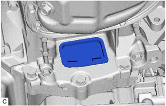
Remove the flywheel housing under cover from the stiffening crankcase assembly.
-
-
REMOVE DRIVE PLATE AND TORQUE CONVERTER ASSEMBLY SETTING BOLT (for CVT)
-
DISCONNECT CLUTCH HOSE (for Manual Transaxle)
-
Using a 10 mm union nut wrench, disconnect the bleeder clutch release tube from the clutch hose.
-
Remove the clip and disconnect the clutch hose from the clutch flexible hose bracket.
-
-
REMOVE FRONT SUSPENSION MEMBER REAR BRACE LH
-
REMOVE FRONT SUSPENSION MEMBER REAR BRACE RH
Tech Tips
Use the same procedure as for the LH side.
-
REMOVE FRONT SUSPENSION CROSSMEMBER SUB-ASSEMBLY
-
REMOVE ENGINE ASSEMBLY WITH TRANSAXLE
-
Set the engine assembly with transaxle on an engine lifter.
Note
-
Using height adjustment attachments and plate lift attachments, keep the engine assembly with transaxle horizontal.
-
Do not position the height adjustment attachments or plate lift attachments under the front crossmember sub-assembly.
-
Do not perform any procedures while the engine assembly is suspended because doing so may cause the engine assembly to drop, resulting in injury. However, the engine assembly needs to be suspended when it is installed to or removed from an engine stand.
-
To prevent the engine assembly from unexpectedly moving, securely support the engine assembly until it is secured to an engine stand.
-
To prevent the oil pan sub-assembly from deforming, do not place any attachments under the oil pan sub-assembly of the engine assembly with transaxle.
-
-
Remove the 2 bolts and disconnect the front engine mounting insulator from the front crossmember sub-assembly.
-
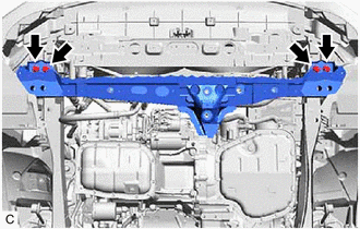
Remove the 4 bolts and front crossmember sub-assembly from the vehicle body.
-
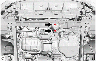
Remove the bolt and 2 nuts and separate the engine mounting insulator sub-assembly RH from the engine mounting bracket RH.
-
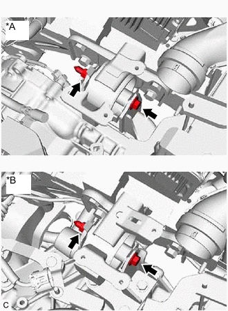
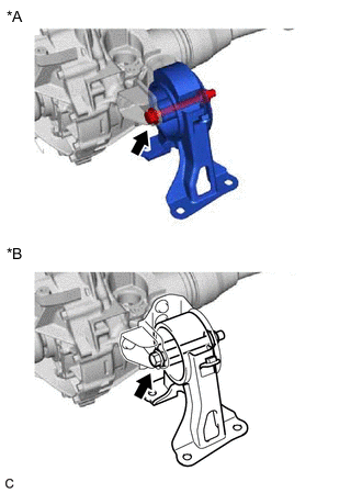
*A for CVT *B for Manual Transaxle Remove the bolt and nut and separate the engine mounting insulator LH from the engine mounting bracket LH.
Note
While holding the nut in place, loosen the bolt.
-
Operate the engine lifter and remove the engine assembly with transaxle from the vehicle.
Note
-
Make sure that the engine assembly with transaxle is clear of all wiring and hoses.
-
While lowering the engine assembly with transaxle from the vehicle, do not allow it to contact the vehicle.
-
-
-
REMOVE WIRE HARNESS CLAMP BRACKET
-
Disconnect the wire harness from the wire harness clamp bracket.
-
Disengage the clamp from the wire harness clamp bracket.
-
Remove the bolt and wire harness clamp bracket from the cylinder head sub-assembly.
-
-
INSTALL ENGINE HANGERS
-
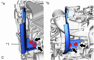
*1 No. 1 Engine Hanger (Part No. 12281-47060) *2 No. 2 Engine Hanger (Part No. 12282-47030) *a Front of Engine (or RH Side of Vehicle) *b Rear of Engine (or LH Side of Vehicle) 
Bolt (Part No. 91552-81030) Install the No. 1 engine hanger and No. 2 engine hanger with the 4 bolts as shown in the illustration.
- Torque:
- 43 N*m { 438 kgf*cm, 32 ft.*lbf }
-
Using an engine sling device and engine lift, secure the engine assembly with transaxle.
Note
-
Pay attention to the angle of the sling device as the engine assembly or No. 1 engine hanger and No. 2 engine hanger may be damaged or deformed if the angle is incorrect.
-
Do not perform any procedures while the engine assembly is suspended because doing so may cause the engine assembly to drop, resulting in injury. However, the engine assembly needs to be suspended when it is installed to or removed from an engine stand.
-
-
-
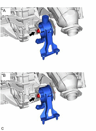
REMOVE FRONT ENGINE MOUNTING INSULATOR
Tech Tips
Perform this procedure only when replacement of the front engine mounting insulator is necessary.
-
*A for CVT *B for Manual Transaxle Remove the bolt, nut and front engine mounting insulator from the front engine mounting bracket.
Note
While holding the nut in place, loosen the bolt.
-
-
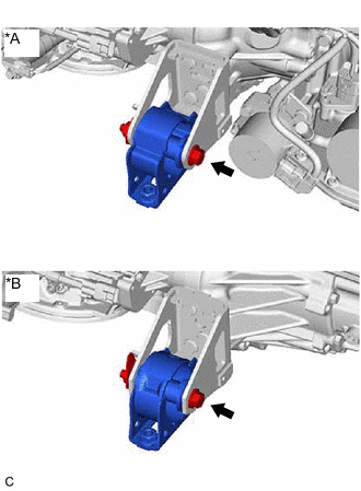
REMOVE REAR ENGINE MOUNTING INSULATOR (for CVT)
Tech Tips
Perform this procedure only when replacement of the rear engine mounting insulator is necessary.
-
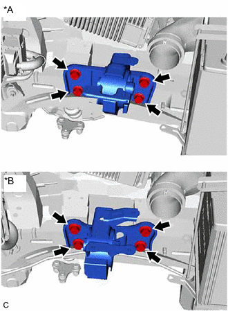
*A Type A *B Type B Remove the bolt and rear engine mounting insulator from the rear engine mounting bracket.
-
-
REMOVE REAR ENGINE MOUNTING INSULATOR (for Manual Transaxle)
Tech Tips
Perform this procedure only when replacement of the rear engine mounting insulator is necessary.
-
*A Type A *B Type B Remove the bolt and rear engine mounting insulator from the rear engine mounting bracket.
-
-
REMOVE ENGINE MOUNTING INSULATOR LH
Tech Tips
Perform this procedure only when replacement of the engine mounting insulator LH is necessary.
-
*A for CVT *B for Manual Transaxle Remove the 4 bolts and engine mounting insulator LH from the vehicle body.
-
-
REMOVE ENGINE MOUNTING INSULATOR SUB-ASSEMBLY RH
Tech Tips
Perform this procedure only when replacement of the engine mounting insulator sub-assembly RH is necessary.
-
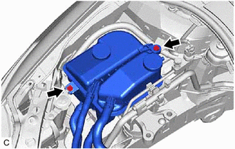
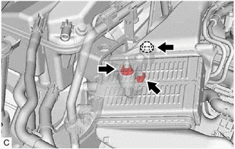
Remove the 2 bolts and disconnect the intercooler reserve tank assembly from the vehicle body.
-
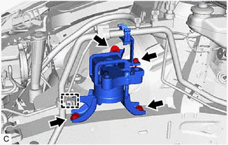
Remove the bolt and cooler pipe clamp bracket from the engine mounting insulator sub-assembly RH.
-
Disconnect the cooler pipe clamp from the engine mounting insulator sub-assembly RH.
-
Remove the 3 bolts and engine mounting insulator sub-assembly RH from the vehicle body.
-
-
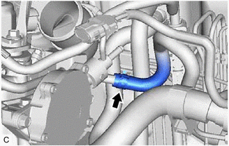
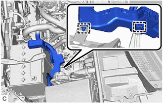
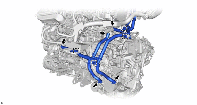
REMOVE WATER HOSE (for CVT)
-
Disengage the 4 clamps from the engine assembly with transaxle.
-
Slide the 5 clips and remove the water hose from the engine assembly with transaxle.
-
-
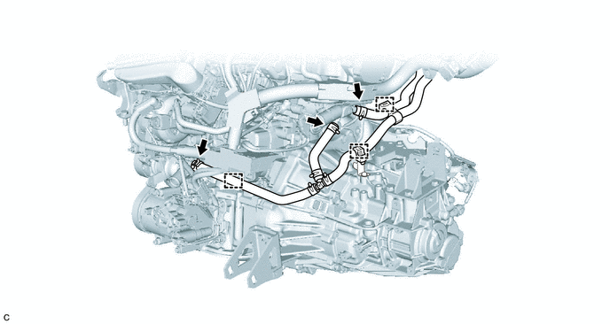
REMOVE WATER HOSE (for Manual Transaxle)
-
Disengage the 3 clamps from the engine assembly with transaxle.
-
Slide the 3 clips and remove the water hose from the engine assembly with transaxle.
-
-
REMOVE FLYWHEEL HOUSING SIDE COVER
w/o Stop And Start System: Click here
for Transaxle CVT with Stop and Start System: Click here
for Transaxle M/T with Stop and Start System: Click here
-
REMOVE STARTER ASSEMBLY
w/o Stop And Start System: Click here
for Transaxle CVT with Stop and Start System: Click here
for Transaxle M/T with Stop and Start System: Click here
-
REMOVE ENGINE WIRE
-
Disconnect all clamps and connectors and remove the engine wire from the engine assembly with transaxle.
-
-
REMOVE CONTINUOUSLY VARIABLE TRANSAXLE ASSEMBLY (for CVT)
-
REMOVE CLUTCH DISC ASSEMBLY (for Manual Transaxle)
-
REMOVE DRIVE PLATE AND RING GEAR SUB-ASSEMBLY (for CVT)
-
REMOVE FLYWHEEL SUB-ASSEMBLY (for Manual Transaxle)
-
REMOVE V-RIBBED BELT
-
REMOVE V-RIBBED BELT TENSIONER ASSEMBLY
-
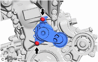
Remove the 2 bolts and V-ribbed belt tensioner assembly from the timing chain cover assembly.
-
-
REMOVE GENERATOR ASSEMBLY
-
REMOVE COMPRESSOR ASSEMBLY WITH PULLEY (w/ Air Conditioning System)
-
REMOVE NO. 1 IDLER PULLEY (w/o Air Conditioning System)
Tech Tips
Perform this procedure only when replacement of the No. 1 idler pulley is necessary.
-
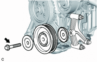
Remove the bolt and No. 1 idler pulley with the 2 idler pulley cover plate from the idler pulley bracket.
-
-
REMOVE NO. 1 IDLER PULLEY SUB-ASSEMBLY (w/o Air Conditioning System)
-
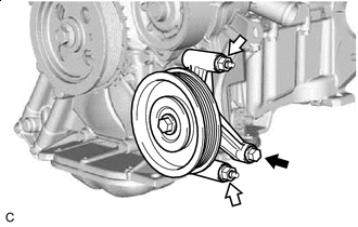
Bolt 
Nut Remove the bolt and 2 nuts.
-
Remove the No. 1 idler pulley sub-assembly.
-
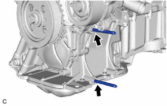
Using an E8 "TORX" socket wrench, remove the 2 stud bolts.
-
-
INSTALL ENGINE ASSEMBLY TO ENGINE STAND
-
Install the engine assembly to an engine stand.
-
-
REMOVE ENGINE HANGERS
-
Remove the 4 bolts, No. 1 engine hanger and No. 2 engine hanger.
-