БЛОК ЦИЛИНДРОВ (для моделей без контроллера свечей накаливания) ПОВТОРНАЯ СБОРКА

PROCEDURE
-
INSTALL OIL JET
-
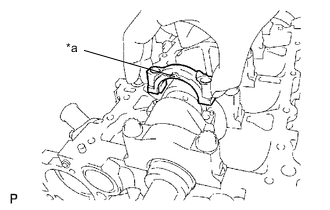
Tap in a new oil jet with the tip of the oil jet aligned with the cylinder block sub-assembly alignment mark.
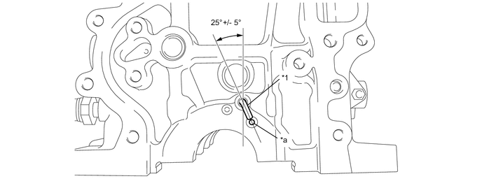
*1 Oil Jet - - *a Alignment Mark - - Note
Do not tap the tip of the oil jet.
-
-
INSTALL NO. 1 OIL NOZZLE SUB-ASSEMBLY
-
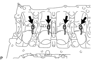
Using a 5 mm hexagon socket wrench, install the 4 No. 1 oil nozzle sub-assemblies with the 4 bolts.
- Torque:
- 9.0 N*m { 92 kgf*cm, 80 in.*lbf }
-
-
INSTALL CRANKSHAFT
Note
The types of No. 1 journal crankshaft bearing and No. 5 journal crankshaft bearing to be used for vehicles w/ Stop And Start System and w/o Stop And Start System are different. Use the correct parts for the vehicle specifications when replacing the crankshaft bearings.
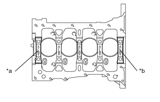
*a No. 1 Journal Crankshaft Bearing *b No. 5 Journal Crankshaft Bearing
-
Install the crankshaft bearing with the oil groove to the cylinder block sub-assembly and the crankshaft bearing to the crankshaft bearing cap.
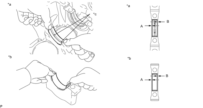
*a Cylinder Block Sub-assembly Side *b Crankshaft Bearing Cap Side *c Oil Groove - - Note
Do not apply engine oil to the contact surface of the cylinder block sub-assembly or the back side of the crankshaft bearings.
Tech Tips
Mass production parts do not have identification marks. If reusing a mass production part, measure the clearance of both sides so that the crankshaft bearing is in the center of the crankshaft bearing cap.
Specified clearance A - B = 0.8 mm (0.0315 in.) or less -
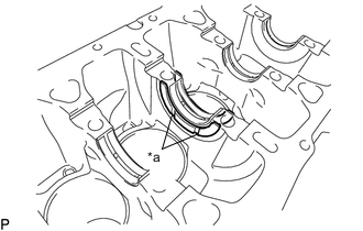
*a Oil Groove Install the 2 upper crankshaft thrust washers onto the cylinder block sub-assembly and the front and back side of the No. 3 journal with the oil groove facing outward.
-
Apply engine oil to the crankshaft bearings, and then install the crankshaft onto the cylinder block sub-assembly.
-
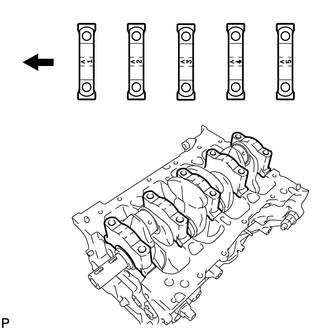

Engine Front Side Examine the front marks and numbers and check that the order is as shown in the illustration. Then, install the crankshaft bearing caps to the cylinder block sub-assembly.
-
Apply a light coat of engine oil to the threads and contact surfaces of the 10 crankshaft bearing cap set bolts.
-
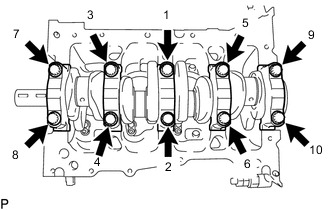
Temporarily tighten the 10 crankshaft bearing cap set bolts in several steps in the order shown in the illustration, and tighten them to the specified torque (*1).
- Torque:
- 60 N*m { 612 kgf*cm, 44 ft.*lbf }
Tech Tips
Check that the crankshaft turns smoothly while tightening the 10 crankshaft bearing cap set bolts.
-
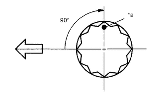
*a Paint Mark 
Engine Front Mark the front of the 10 crankshaft bearing cap set bolts with paint.
-
Tighten the 10 crankshaft bearing cap set bolts by 90° in the same order as in step (*1).
-
Check that each paint mark is now at a 90° angle to the front.
-
-
INSTALL WITH PIN PISTON SUB-ASSEMBLY
-
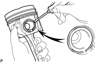
Using a small screwdriver, install a new snap ring at one end of the piston pin hole.
-
*a Front Mark Align the front marks of the piston and connecting rod cap.
-
Apply a light coat of engine oil to the piston pin, and then push the piston pin into the hole of the piston and connecting rod.
-
Using a small screwdriver, install a new snap ring on the other end of the piston pin hole.
Note
Do not change the combinations of the pistons and piston pins so that they can be returned to their original location when reassembling.
-
-
INSTALL CONNECTING ROD BEARING
-
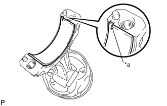
*a Oil Groove Align the connecting rod bearing and oil grooves, and then install the connecting rod bearing to the connecting rod.
Note
Do not apply engine oil to the contact surfaces of the connecting rod, connecting rod cap or the back side of the connecting rod bearing.
-
-
INSTALL PISTON RING SET
-
Install oil ring (expander) by hand.
-
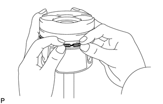
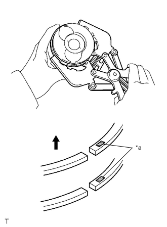
*a Expander End *b Side Rail End Using a piston ring expander, install the oil ring (side rail) as shown in the illustration.
Tech Tips
The upper and lower oil rings are the same.
-
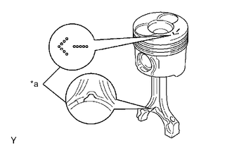
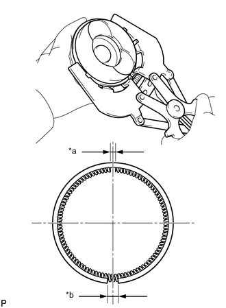
*a Code Mark Upward Using a piston ring expander, install the No. 1 compression ring and No. 2 compression ring with the code marks as shown in the illustration.
Part Code Mark No. 1 compression ring 1R No. 2 compression ring 2R Oil ring - -
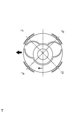
*1 No. 1 Compression Ring *2 No. 2 Compression Ring *a Oil Ring Position A *b Oil Ring Position B Engine Front Position the piston rings so that the ring ends are as shown in the illustration.
Note
Make sure that the gap in the oil ring is placed at either position A or B.
-
-
INSTALL PISTON SUB-ASSEMBLY WITH CONNECTING ROD
-
*a Front Mark Apply engine oil to the cylinder walls, pistons and surfaces of the connecting rod bearings.
-
Check that the gap in the piston ring is positioned correctly.
-
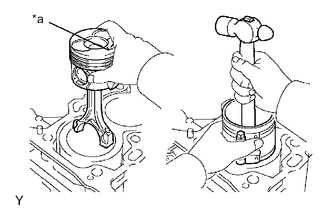
Check the front marks. Using a piston ring compressor, install the piston with pin sub-assembly with connecting rod.
-
*a Front Mark Check that the connecting rod and connecting rod cap are in the correct combination and that the front marks are facing correctly, and then install the connecting rod cap to the connecting rod.
Note
The connecting rods and connecting rod caps should be reinstalled in their original combinations.
-
Apply a light coat of engine oil to the threads and under the heads of the connecting rod bolts.
-
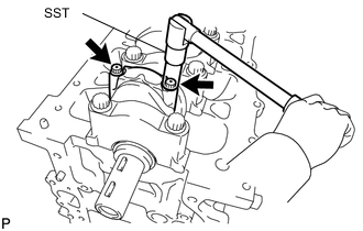
Using SST, temporarily tighten and then tighten the connecting rod bolts to the specified torque.
- SST
- 09205-16011
- Torque:
- 15 N*m { 153 kgf*cm, 11 ft.*lbf }
-
*a Paint Mark Engine Front Mark the front of the connecting rod bolts with paint.
-
Tighten the connecting rod bolts by additional 90°.
-
Check that each paint mark is now at a 90° angle to the front.
-
Check that the crankshaft turns smoothly.
-
-
INSTALL TUBE CONNECTOR
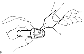
*a Adhesive
-
Apply adhesive to 2 or 3 threads of the tube connector.
Adhesive Toyota Genuine Adhesive 1324, Three Bond 1324 or equivalent -
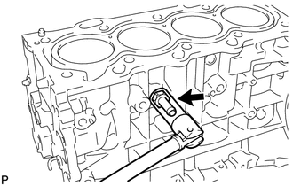
Using a 14 mm deep socket wrench, install the tube connector.
- Torque:
- 25 N*m { 255 kgf*cm, 18 ft.*lbf }
-