БЛОК ЦИЛИНДРОВ (для моделей с контроллером свечей накаливания) ПРОВЕРКА

PROCEDURE
-
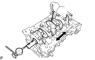
INSPECT CONNECTING ROD THRUST CLEARANCE
-
Install the connecting rod cap.
-
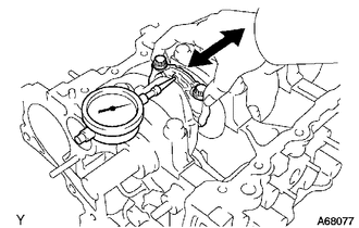
Using a dial indicator, measure the thrust clearance of the connecting rod sub-assembly while moving the connecting rod sub-assembly back and forth.
Standard Thrust Clearance 0.16 to 0.36 mm (0.00630 to 0.0142 in.) Maximum Thrust Clearance 0.36 mm (0.0142 in.) If the thrust clearance is more than the maximum, replace the connecting rod sub-assembly. If necessary, replace the crankshaft.
-
-
INSPECT CONNECTING ROD OIL CLEARANCE
-
Clean the connecting rod bearing and crank pin.
-
Check that the connecting rod bearing and crank pin are not excessively worn or scratched.
-
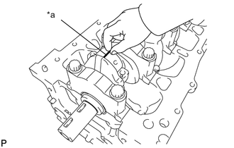
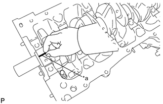
*a Plastigage Lay a strip of Plastigage across the crank pin.
-
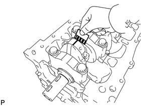
Install the connecting rod cap.
Note
Do not turn the crankshaft.
-
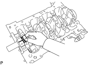
Remove the connecting rod cap.
-
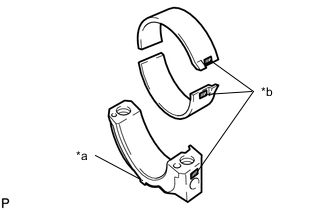
*a Front Mark *b Number Mark Measure the Plastigage at its widest point.
Standard Oil Clearance 0.014 to 0.038 mm (0.000551 to 0.00150 in.) Maximum Oil Clearance 0.065 mm (0.00256 in.) Note
Completely remove the Plastigage after the measurement.
If the clearance is more than the maximum, select and install a replacement connecting rod bearing. If necessary, replace the crankshaft.
Reference Number Mark Connecting Rod
Diameter
Center Bearing
Thickness
Oil Clearance 1 47.000 to 47.008 mm
(1.85039 to 1.85071 in.)
1.489 to 1.493 mm
(0.05862 to 0.05878 in.)
0.014 to 0.038 mm
(0.000551 to 0.00150 in.)
2 47.009 to 47.016 mm
(1.85074 to 1.85102 in.)
1.494 to 1.497 mm
(0.05882 to 0.05894 in.)
3 47.017 to 47.024 mm
(1.85106 to 1.85133 in.)
1.498 to 1.501 mm
(0.05898 to 0.05909 in.)
-
-
INSPECT CRANKSHAFT THRUST CLEARANCE
-
Install the crankshaft.
-
Using a dial indicator, measure the thrust clearance of the crankshaft while moving a screwdriver back and forth between the crankshaft and crankshaft bearing cap.
Standard Thrust Clearance 0.04 to 0.24 mm (0.00157 to 0.00945 in.) Maximum Thrust Clearance 0.30 mm (0.0118 in.) Upper Crankshaft Thrust Washer Thickness 2.43 to 2.48 mm (0.0957 to 0.0976 in.) If the thrust clearance is more than the maximum, replace the upper crankshaft thrust washers or crankshaft.
-
-
INSPECT CYLINDER BLOCK FOR WARPAGE
-
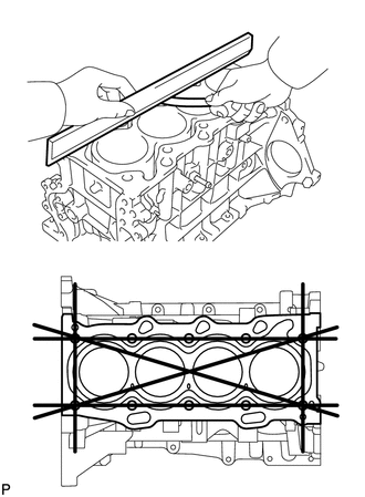
Using a precision straightedge and feeler gauge, measure the warpage of the top surface of the cylinder block sub-assembly.
Maximum Warpage 0.05 mm (0.00197 in.) If the warpage is more than the maximum, replace the cylinder block sub-assembly.
-
-
INSPECT CYLINDER BORE
-
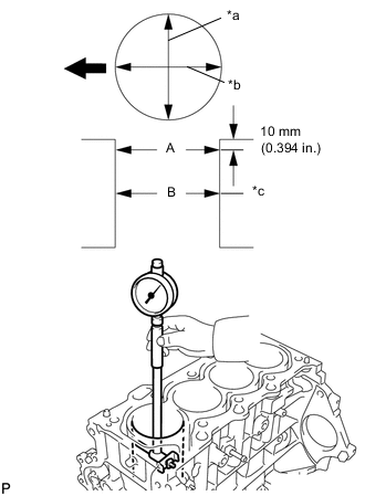
*a Thrust Direction *b Axial Direction *c Center 
Engine Front Using a cylinder gauge, measure the cylinder bore diameter at positions (A) and (B) in the thrust and axial directions.
Standard Diameter 73.000 to 73.013 mm (2.8740 to 2.8745 in.) Maximum Diameter 73.13 mm (2.8791 in.) If the diameter is more than the maximum, replace the cylinder block sub-assembly.
-
-
INSPECT PISTON DIAMETER
-
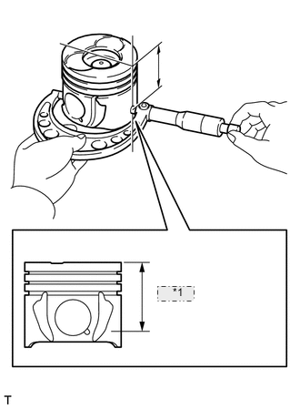
*1 50.4 mm Using a micrometer, measure the piston diameter at right angles to the piston pin center line, and at a position 50.4 mm (1.98 in.) from the piston end.
Standard Piston Diameter 72.936 to 73.000 mm (2.8715 to 2.8740 in.) If the piston diameter is not as specified, replace the piston with pin sub-assembly.
-
-
INSPECT PISTON OIL CLEARANCE
-
Subtract the piston diameter measurement from the cylinder bore minimum diameter measurement to calculate the piston clearance.
Standard Oil Clearance 0.050 to 0.077 mm (0.00197 to 0.00303 in.) Maximum Oil Clearance 0.08 mm (0.00315 in.) If the piston oil clearance is more than the maximum, replace the piston with pin sub-assembly or cylinder block sub-assembly.
-
Subtract the piston pin diameter measurement from the bushing inside diameter measurement.
Standard Oil Clearance 0.007 to 0.015 mm (0.0003 to 0.0006 in.) Maximum Oil Clearance 0.05 mm (0.0020 in.) If the oil clearance is more than maximum, replace the bushing. If necessary, replace the piston and piston pin as a set.
-
-
INSPECT RING GROOVE CLEARANCE
-
Using a feeler gauge, measure the clearance between the piston ring and ring groove around the piston.
Standard Ring Groove Clearance Ring Standard No. 1 Compression Ring 0.110 to 0.150 mm
(0.00433 to 0.00591 in.)
No. 2 Compression Ring 0.070 to 0.110 mm
(0.00276 to 0.00433 in.)
Oil Ring 0.030 to 0.070 mm
(0.00118 to 0.00276 in.)
If the clearance is not as specified, replace the piston with pin sub-assembly or piston ring set.
-
-
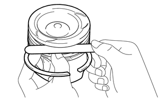
INSPECT PISTON RING END GAP
-
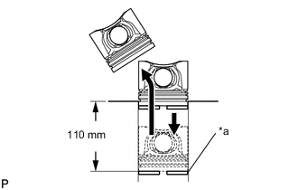
*a Piston Ring Using a piston, push the piston ring until it is 110 mm (4.33 in.) from the top of the cylinder block sub-assembly.
-
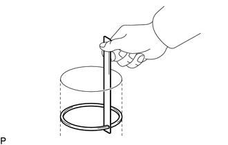
Using a feeler gauge, measure the end gap.
Standard End Gap Ring Standard Maximum No. 1 Compression Ring 0.17 to 0.22 mm
(0.00669 to 0.00866 in.)
0.42 mm
(0.0165 in.)
No. 2 Compression Ring 0.65 to 0.75 mm
(0.0256 to 0.0295 in.)
0.80 mm
(0.0315 in.)
Oil Ring 0.10 to 0.30 mm
(0.00394 to 0.0118 in.)
0.70 mm
(0.0276 in.)
If the end gap is more than the maximum, replace the piston ring set.
-
-
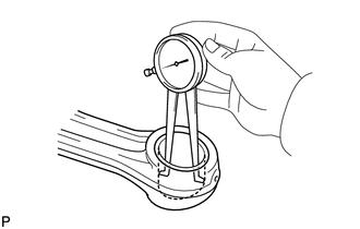
INSPECT PISTON PIN OIL CLEARANCE
-
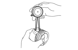
Using a caliper gauge, measure the inside diameter of the piston pin hole.
Standard Piston Pin Hole Inside Diameter Item Specified Condition Mark (A) 27.019 to 27.023 mm
(1.06374 to 1.06390 in.)
Mark (B) 27.023 to 27.027 mm
(1.06390 to 1.06405 in.)
Mark (C) 27.027 to 27.031 mm
(1.06405 to 1.06421 in.)
-
Using a micrometer, measure the diameter of the piston pin.
Standard Piston Pin Diameter Item Specified Condition Mark (A) 27.008 to 27.012 mm
(1.06330 to 1.06346 in.)
Mark (B) 27.013 to 27.016 mm
(1.06350 to 1.06362 in.)
Mark (C) 27.017 to 27.020 mm
(1.06366 to 1.06378 in.)
Note
Do not change the combinations of the pistons and piston pins so that they can be returned to their original locations when reassembling.
-
Using a caliper gauge, measure the inside diameter of the connecting rod sub-assembly.
Standard Connecting Rod Inside Diameter Item Specified Condition Mark (A) 27.022 to 27.026 mm
(1.06386 to 1.06401 in.)
Mark (B) 27.027 to 27.030 mm
(1.06405 to 1.06417 in.)
Mark (C) 27.031 to 27.034 mm
(1.06421 to 1.06433 in.)
If the diameter is more than the maximum, replace the connecting rod sub-assembly.
-
-
INSPECT CONNECTING ROD SUB-ASSEMBLY
-
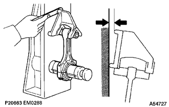
Using a rod aligner and feeler gauge, check the connecting rod sub-assembly alignment.
-
Check for misalignment.
Maximum Misalignment 0.05 mm (0.00197 in.) per 100 mm (3.94 in.) If the misalignment is more than the maximum, replace the connecting rod sub-assembly.
-
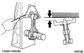
Check for twist.
Maximum Twist 0.15 mm (0.00591 in.) per 100 mm (3.94 in.) If the twist is more than the maximum, replace the connecting rod sub-assembly.
-
-
-
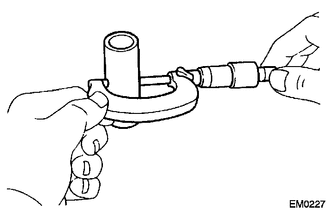
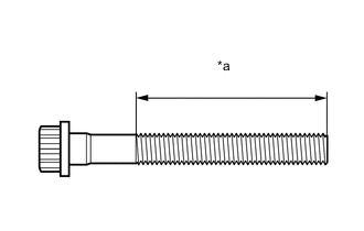
INSPECT CONNECTING ROD BOLT
-
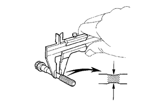
Using a vernier caliper, measure the diameter at the position shown in the illustration.
Standard Diameter 6.6 to 6.7 mm (0.260 to 0.264 in.) Minimum Diameter 6.4 mm (0.252 in.) If the diameter is less than the minimum, replace the connecting rod bolt.
-
-
INSPECT CRANKSHAFT
-
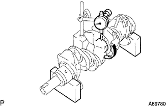
Inspect for runout.
-
Using a dial indicator and V-blocks, measure the runout of the crankshaft.
Maximum Runout 0.015 mm (0.000591 in.) If the runout is more than the maximum, replace the crankshaft.
-
-
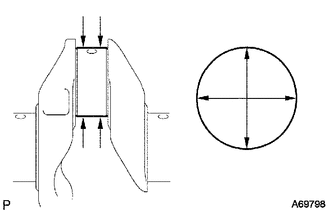
Inspect the main journals.
-
Using a micrometer, measure the diameter of each main journal as shown in the illustration.
Standard Diameter 45.988 to 46.000 mm (1.8104 to 1.8110 in.) If the diameter is not as specified, check the oil clearance. If necessary, replace the crankshaft.
-
Check the taper and out-of-round of each main journal.
Maximum Taper and Out-of-Round 0.02 mm (0.000787 in.) If the taper or out-of-round is greater than the maximum, replace the crankshaft.
-
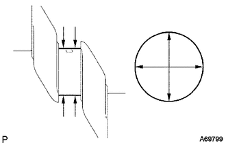
Using a micrometer, measure the diameter of each crank pin as shown in the illustration.
Standard Diameter 43.992 to 44.000 mm (1.7320 to 1.7323 in.) If the diameter is not as specified, check the oil clearance. If necessary, replace the crankshaft.
-
Check the taper and out-of-round of each crank pin.
Maximum Taper and Out-of-Round 0.02 mm (0.000787 in.) If the taper or out-of-round is greater than the maximum, replace the crankshaft.
-
-
-
INSPECT CRANKSHAFT BEARING CAP SET BOLT
-
*a Measurement Area Using a vernier caliper, measure the diameter of the crankshaft bearing cap set bolt at several points within the area shown in the illustration.
Standard Diameter 10.8 to 11.0 mm (0.425 to 0.433 in.) Minimum Diameter 10.6 mm (0.417 in.) If the diameter is less than the minimum, replace the crankshaft bearing cap set bolt.
-
-
INSPECT CRANKSHAFT OIL CLEARANCE
-
Install the crankshaft bearing.
-
Place the crankshaft on the cylinder block sub-assembly.
-
*a Plastigage Lay a strip of Plastigage across each crankshaft journal.
-
Install the crankshaft bearing cap.
Note
Do not turn the crankshaft.
-
Remove the crankshaft bearing cap.
-
Measure the Plastigage at its widest point.
Standard Oil Clearance 0.010 to 0.023 mm (0.000394 to 0.000906 in.) Maximum Oil Clearance 0.07 mm (0.00276 in.) Note
Remove the Plastigage completely after the measurement.
If the oil clearance is greater than the maximum, replace the crankshaft bearings.
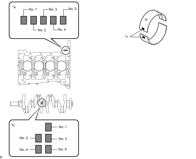
*a Cylinder Block Sub-assembly Number *b Crank Journal Number *c Crankshaft Bearing Number - - Tech Tips
-
To select the correct crankshaft bearing size, calculate the crankshaft bearing number by adding together the numbers imprinted on the cylinder block sub-assembly and crank journal.
-
Example:
Imprinted number on the cylinder block sub-assembly is 3.
Imprinted number on the crank journal is 4.
3 + 4 = 7
Select a crankshaft bearing number 3.
Number Cylinder Block Main Journal Bore Diameter Crank Main Journal Diameter 0 50.000 to 50.002 mm
(1.96850 to 1.96858 in.)
45.999 to 46.000 mm
(1.81098 to 1.81102 in.)
1 50.003 to 50.004 mm
(1.96862 to 1.96866 in.)
45.997 to 45.998 mm
(1.81090 to 1.81094 in.)
2 50.005 to 50.006 mm
(1.96870 to 1.96874 in.)
45.995 to 45.996 mm
(1.81082 to 1.81086 in.)
3 50.007 to 50.009 mm
(1.96878 to 1.96885 in.)
45.993 to 45.994 mm
(1.81074 to 1.81078 in.)
4 50.010 to 50.011 mm
(1.96889 to 1.96893 in.)
45.991 to 45.992 mm
(1.81067 to 1.81071 in.)
5 50.012 to 50.013 mm
(1.96897 to 1.96901 in.)
45.989 to 45.990 mm
(1.81059 to 1.81063 in.)
6 50.014 to 50.016 mm
(1.96905 to 1.96913 in.)
- Cylinder Block Sub-assembly
Number + Crank
Journal Number
Crankshaft Bearing Number Crankshaft Bearing Thickness Oil Clearance 0 to 2 1 1.992 to 1.995 mm
(0.07843 to 0.07854 in.)
0.010 to 0.023 mm
(0.000394 to 0.000906 in.)
3 to 5 2 1.996 to 1.998 mm
(0.07858 to 0.07866 in.)
6 to 8 3 1.999 to 2.001 mm
(0.07870 to 0.07878 in.)
9 to 11 4 2.002 to 2.004 mm
(0.07882 to 0.07890 in.)
-
-