БЛОК ДВИГАТЕЛЯ (для моделей без контроллера свечей накаливания) ПРОВЕРКА

PROCEDURE
-
INSPECT OIL CHECK VALVE SUB-ASSEMBLY
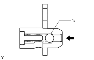
*a Ball
-
Push the ball of the oil check valve sub-assembly to check if it is stuck.
If the check valve is stuck, replace the oil check valve sub-assembly.
-
-
INSPECT NO. 1 VALVE ROCKER ARM SUB-ASSEMBLY
-
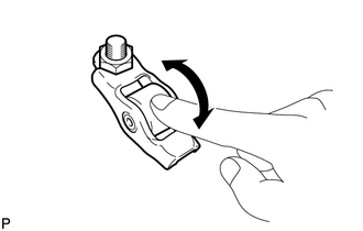
Turn the roller by hand to check that it turns smoothly.
If the roller does not turn smoothly, replace the No. 1 valve rocker arm sub-assembly.
-
-
INSPECT CHAIN SUB-ASSEMBLY
-
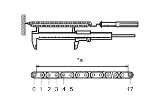
*a Measurement Area Using a spring scale, apply 140 N (14 kgf, 31.5 lbf) to the chain sub-assembly then measure its length.
Maximum chain length 156.5 mm (6.161 in.) Tech Tips
Measure the length in at least 3 places and calculate the average length.
If the length is greater than the maximum, replace the chain sub-assembly.
-
-
INSPECT NO. 2 CHAIN SUB-ASSEMBLY
-
*a Measurement Area Using a spring scale, apply 140 N (14 kgf, 31.5 lbf) to the No. 2 chain sub-assembly then measure its length.
Maximum chain length 116.5 mm (4.586 in.) Tech Tips
Measure the length in at least 3 places and calculate the average length.
If the length is greater than the maximum, replace the No. 2 chain sub-assembly.
-
-
INSPECT NO. 1 CHAIN TENSIONER ASSEMBLY
-
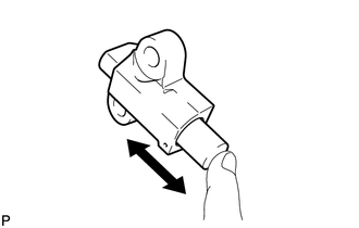
Check that the plunger moves smoothly.
-
-
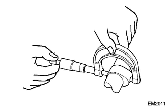
INSPECT CAMSHAFT TIMING SPROCKET
-
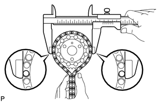
Place the chain sub-assembly around the camshaft timing sprocket.
-
Using a vernier caliper, measure the diameter of the camshaft timing sprocket including the chain sub-assembly.
Minimum sprocket diameter (w/ chain) 132.5 mm (5.216 in.) Note
The vernier caliper must be in contact with the chain sub-assembly rollers when measuring.
If the diameter is less than the minimum, replace the camshaft timing sprocket.
-
-
INSPECT CRANKSHAFT TIMING SPROCKET
-
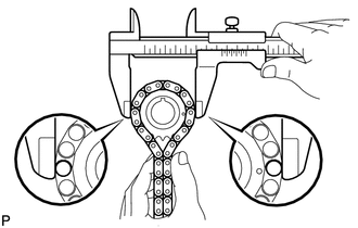
Place the chain sub-assembly around the crankshaft timing sprocket.
-
Using a vernier caliper, measure the diameter of the crankshaft timing sprocket including the chain sub-assembly.
Minimum sprocket diameter (w/ chain) 69.0 mm (2.716 in.) Note
The vernier caliper must be in contact with the chain sub-assembly rollers when measuring.
If the diameter is less than the minimum, replace the crankshaft timing sprocket.
-
-
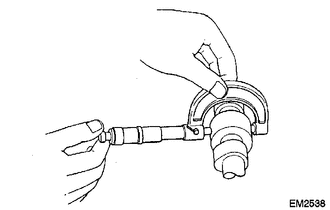
INSPECT OIL PUMP DRIVE GEAR
-
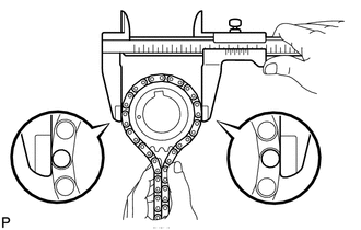
Place the No. 2 chain sub-assembly around the oil pump drive gear.
-
Using a vernier caliper, measure the diameter of the oil pump drive gear including the No. 2 chain sub-assembly.
Minimum sprocket diameter (w/ chain) 57.6 mm (2.267 in.) Note
The vernier caliper must be in contact with the No. 2 chain sub-assembly rollers when measuring.
If the diameter is less than the minimum, replace the oil pump drive gear.
-
-
INSPECT OIL PUMP DRIVE SHAFT GEAR
-
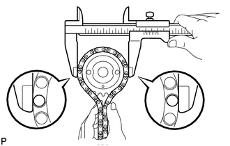
Place the No. 2 chain sub-assembly around the oil pump drive shaft gear.
-
Using a vernier caliper, measure the diameter of the oil pump drive shaft gear including the No. 2 chain sub-assembly.
Minimum sprocket diameter (w/ chain) 53.5 mm (2.106 in.) Note
The vernier caliper must be in contact with the No. 2 chain sub-assembly rollers when measuring.
If the diameter is less than the minimum, replace the oil pump drive shaft gear.
-
-
INSPECT CHAIN TENSIONER SLIPPER
-
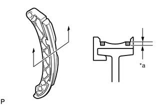
*a Wear Using a vernier caliper, measure the wear of the chain tensioner slipper.
Maximum wear 1.0 mm (0.0394 in.) If the wear is greater than the maximum, replace the chain tensioner slipper.
-
-
INSPECT NO. 1 CHAIN VIBRATION DAMPER
-
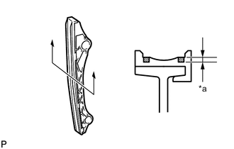
*a Wear Using a vernier caliper, measure the wear of the No. 1 chain vibration damper.
Maximum wear 1.0 mm (0.0394 in.) If the wear is greater than the maximum, replace the No. 1 chain vibration damper.
-
-
INSPECT CHAIN TENSIONER PLATE
-
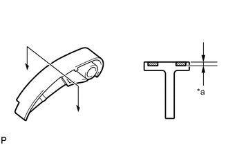
*a Wear Using a vernier caliper, measure the wear of the chain tensioner plate.
Maximum wear 1.0 mm (0.0394 in.) If the wear is greater than the maximum, replace the chain tensioner plate.
-
-
INSPECT CAMSHAFT
-
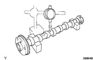
Inspect the runout.
-
Place the camshaft on V-blocks.
-
Using a dial indicator, measure the runout of the camshaft at the center journal.
Maximum runout 0.03 mm (0.00118 in.) If the runout is greater than the maximum, replace the camshaft.
-
-
Inspect the height of the cam lobes.
-
Using a micrometer, measure the cam lobe height.
Standard cam lobe height Intake 34.484 to 34.584 mm (1.3576 to 1.3616 in.) Exhaust 34.773 to 34.873 mm (1.3690 to 1.3730 in.) Minimum cam lobe height Intake 34.064 mm (1.3411 in.) Exhaust 34.353 mm (1.3525 in.) If the cam lobe height is less than the minimum, replace the camshaft.
-
-
Inspect the diameter of the cam journals.
-
Using a micrometer, measure the cam journal diameter.
Standard cam journal diameter 23.979 to 23.995 mm (0.9441 to 0.9447 in.) If the cam journal diameter is not as specified, check the oil clearance.
-
-
-
INSPECT CYLINDER HEAD SET BOLT
-
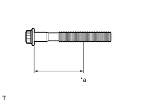
*a Measurement Point Using a vernier caliper, measure the diameter of the threads at the measurement point.
Standard diameter 11.5 to 12.0 mm (0.453 to 0.472 in.) Minimum diameter 11.2 mm (0.441 in.) Measurement point (distance from the seat) 123 mm (4.84 in.) If the diameter is less than the minimum, replace the cylinder head set bolt. Failure to do so may lead to engine damage.
If there is any thread deformation, replace the cylinder head set bolt with a new one.
-
-
INSPECT EXHAUST MANIFOLD
-
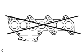
Using a precision straightedge and feeler gauge, measure the warpage of the surface that contacts the cylinder head sub-assembly.
Maximum warpage 0.7 mm (0.0276 in.) If the warpage is more than the maximum, replace the exhaust manifold.
-