БЛОК ДВИГАТЕЛЯ (для моделей без контроллера свечей накаливания) СНЯТИЕ

PROCEDURE
-
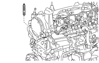
REMOVE ENGINE COVER BRACKET (w/ No. 1 Engine Cover)
-
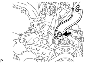
Remove the bolt and engine cover bracket from the engine mounting bracket RH.
-
-
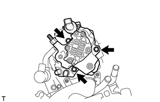
REMOVE GENERATOR ASSEMBLY
-
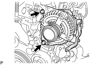
Remove the 2 bolts and generator assembly.
-
-
REMOVE GENERATOR BRACKET
-
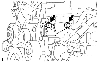
Remove the 2 bolts and generator bracket from the cylinder block sub-assembly.
-
-
REMOVE EGR WITH COOLER PIPE ASSEMBLY
-
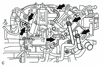
Disconnect the 3 vacuum transmitting hoses from the vacuum switching valve assembly and turbo pressure sensor.
-
Disconnect the vacuum hose from the EGR with cooler pipe assembly.
-
Disconnect the No. 2 oil cooler hose from the EGR with cooler pipe assembly.
-
Disconnect the No. 2 water by-pass hose from the EGR with cooler pipe assembly.
-
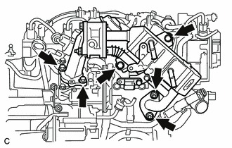
Remove the 4 bolts, 2 nuts and EGR with cooler pipe assembly.
-
Remove the 2 gaskets from the cylinder head sub-assembly and electric EGR control valve assembly.
-
-
REMOVE NO. 1 EGR COOLER BRACKET
-
Remove the 2 bolts and No. 1 EGR cooler bracket from the cylinder head sub-assembly.
-
-
REMOVE HARNESS BRACKET
-
REMOVE EGR VALVE (ELECTRIC EGR CONTROL VALVE ASSEMBLY)
-
REMOVE ENGINE OIL LEVEL DIPSTICK
-
Remove the engine oil level dipstick.
-
-
REMOVE ENGINE OIL LEVEL DIPSTICK GUIDE
-
Remove the bolt and engine oil level dipstick guide.
-
Remove the O-ring from the engine oil level dipstick guide.
-
-
REMOVE INTAKE AIR CONNECTOR WITH DIESEL THROTTLE BODY
-
Disconnect the vacuum transmitting hose from the hose clamp.
-
Remove the 2 bolts, 2 nuts and intake air connector with diesel throttle body.
-
Remove the intake air connector gasket from the cylinder head sub-assembly.
-
-
REMOVE NO. 1 INJECTION PIPE SUB-ASSEMBLY
-
REMOVE NO. 2 INJECTION PIPE SUB-ASSEMBLY
-
REMOVE NO. 3 INJECTION PIPE SUB-ASSEMBLY
-
REMOVE NO. 1 GLOW PLUG CONNECTOR
-
Remove the 4 screw grommets.
-
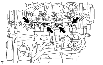
Remove the 4 nuts and No. 1 glow plug connector.
-
-
REMOVE GLOW PLUG ASSEMBLY
-
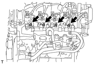
Remove the 4 glow plug assemblies.
-
-
REMOVE NO. 2 INTAKE MANIFOLD INSULATOR
-
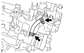
REMOVE NOZZLE LEAKAGE PIPE SET CLAMP
-
Remove the 3 nozzle leakage pipe set clamps from the nozzle leakage pipe assembly.
-
-
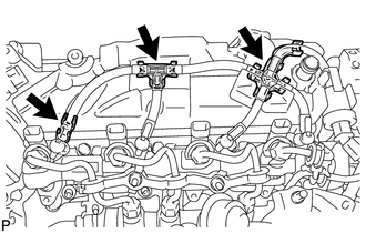
REMOVE NOZZLE LEAKAGE PIPE ASSEMBLY
-
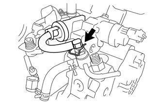
Remove the retainer spring and disconnect the nozzle leakage pipe assembly from the supply pump assembly.
-
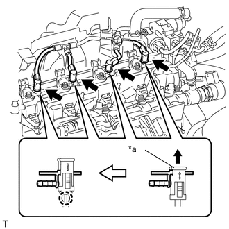
*a Lock Bush Pull up the lock bush as shown in the illustration and remove the nozzle leakage pipe assembly.
Note
Do not remove the nozzle leakage pipe assembly by pulling the hose. Remove it by holding the lock bush.
-
-
REMOVE NO. 1 NOZZLE HOLDER CLAMP
-
REMOVE NOZZLE HOLDER CLAMP SEAT
-
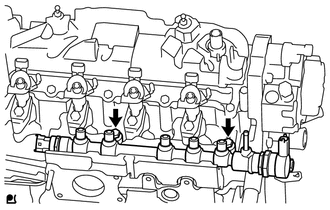
REMOVE INJECTOR ASSEMBLY
-
REMOVE INJECTION NOZZLE SEAT
-
REMOVE FUEL INLET PIPE SUB-ASSEMBLY
-
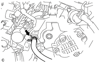
REMOVE NO. 2 FUEL HOSE
-
Remove the No. 2 fuel hose.
-
-
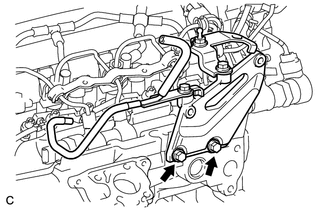
REMOVE SUPPLY PUMP ASSEMBLY
-
Disconnect the No. 1 fuel hose from the supply pump assembly.
-
Remove the 3 bolts and supply pump assembly.
-
Remove the O-ring from the supply pump assembly.
-
-
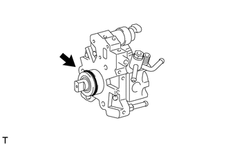
REMOVE NO. 1 SUPPLY PUMP DRIVE COUPLING
-
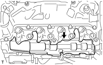
REMOVE COMMON RAIL ASSEMBLY
-
Remove the 2 bolts and common rail assembly from the cylinder head sub-assembly.
Note
Do not remove the fuel pressure sensor and fuel pressure regulator.
-
-
REMOVE NO. 1 INTAKE MANIFOLD INSULATOR
-
Remove the No. 1 intake manifold insulator.
-
-
REMOVE NO. 2 CYLINDER HEAD COVER
-
Remove the No. 2 cylinder head cover.
-
-
REMOVE OIL COOLER HOSE
-
Remove the oil cooler hose.
-
-
REMOVE NO. 2 OIL COOLER HOSE
-
Remove the 2 hose clamps.
-
Disconnect the 2 hose clamps and remove the No. 2 oil cooler hose.
-
-
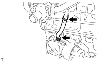
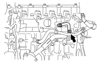
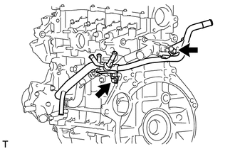
REMOVE NO. 4 WATER BY-PASS HOSE
-
Remove the No. 4 water by-pass hose from the inlet water pipe.
-
-
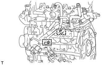
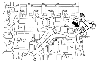
REMOVE NO. 3 WATER BY-PASS HOSE
-
Remove the No. 3 water by-pass hose from the water by-pass pipe sub-assembly.
-
-
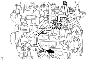
REMOVE NO. 2 WATER BY-PASS HOSE
-
Remove the No. 2 water by-pass hose from the water by-pass pipe sub-assembly.
-
-
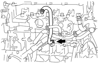
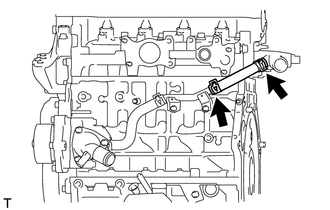
REMOVE WATER BY-PASS HOSE
-
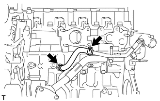
Remove the water by-pass hose.
-
-
REMOVE WATER BY-PASS PIPE SUB-ASSEMBLY
-
Remove the 2 hose clamps from the water by-pass pipe sub-assembly.
-
Remove the 2 bolts and water by-pass pipe sub-assembly.
-
Remove the O-ring from the water by-pass pipe sub-assembly.
-
-
REMOVE INLET WATER HOSE RH
-
Remove the inlet water hose RH.
-
-
REMOVE INLET WATER HOSE LH
-
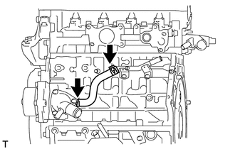
Remove the inlet water hose LH.
-
-
REMOVE INLET WATER PIPE
-
Remove the 2 bolts and inlet water pipe from the cylinder head sub-assembly.
-
-
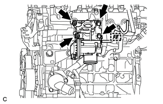
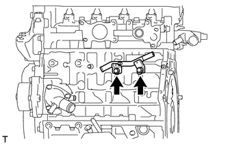
REMOVE VACUUM PUMP ASSEMBLY
-
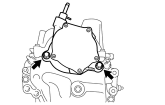
Remove the 2 bolts and vacuum pump assembly.
-
Remove the 2 O-rings from the vacuum pump assembly.
-
-
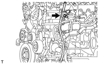
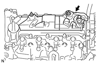
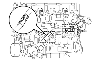
REMOVE CAMSHAFT POSITION SENSOR
-
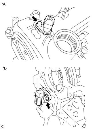
*A w/o Stop And Start System *B w/ Stop And Start System Remove the bolt and camshaft position sensor.
-
-
REMOVE HOLE PLUG
-
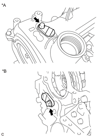
*A w/ Stop And Start System *B w/o Stop And Start System Remove the bolt and hole plug.
-
-
REMOVE V-RIBBED BELT TENSIONER ASSEMBLY
-
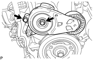
Remove the 2 bolts and V-ribbed belt tensioner assembly.
-
-
REMOVE HARNESS BRACKET
-
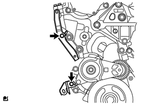
Remove the 2 bolts and 2 harness brackets.
-
-
REMOVE NO. 5 ENGINE COVER
-
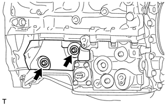
Remove the 2 bolts, 2 washer plates and No. 5 engine cover.
-
-
REMOVE NO. 2 OIL PAN COVER SILENCER
-
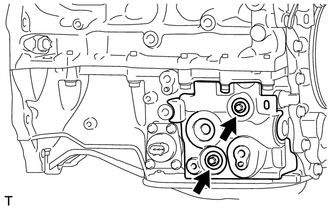
Remove the 2 bolts, 2 washer plates and No. 2 oil pan cover silencer.
-
-
REMOVE OIL PAN COVER
-
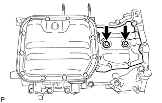
Remove the 2 bolts, 2 washer plates and oil pan cover.
-
-
REMOVE STUD BOLT
-
Using an 8 mm socket wrench, remove the 2 stud bolts from the engine mounting bracket RH.
-