ГОЛОВКА БЛОКА ЦИЛИНДРОВ (для моделей с контроллером свечей накаливания) ЗАМЕНА

PROCEDURE
-
REPLACE INTAKE VALVE GUIDE BUSH
-
Heat the cylinder head sub-assembly to between 80 and 100°C (176 and 212°F).
CAUTION:
Make sure not to burn yourself.
-
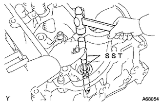
Using SST and a hammer, tap out the intake valve guide bush to the combustion chamber side.
- SST
- 09201-10000 ( 09201-01050 )
- 09950-70010
-

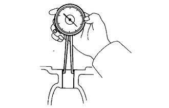
Using a caliper gauge, measure the intake valve guide bush bore diameter of the cylinder head sub-assembly.
Standard Intake Valve Guide Bush Bore Diameter 10.985 to 11.006 mm (0.4325 to 0.4333 in.) Tech Tips
-
If the intake valve guide bush bore diameter is as specified, install a standard intake valve guide bush.
-
If the intake valve guide bush bore diameter is not as specified, correct it to 11.035 to 11.056 mm (0.4344 to 0.4353 in.) and install the oversize intake valve guide bush.
Bush Size Specified Condition STD 10.985 to 11.006 mm (0.4325 to 0.4333 in.) O/S 0.05 11.035 to 11.056 mm (0.4344 to 0.4353 in.)
-
-
Heat the cylinder head sub-assembly to between 80 and 100°C (176 and 212°F).
CAUTION:
Make sure not to burn yourself.
-
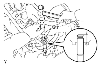
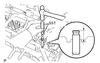
Using SST and a hammer, tap in a new intake valve guide bush to the specified protrusion height.
- SST
- 09201-10000 ( 09201-01050 )
- 09950-70010
Standard Protrusion Height 15.9 to 16.7 mm (0.626 to 0.657 in.) -
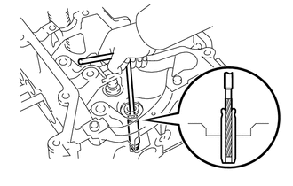
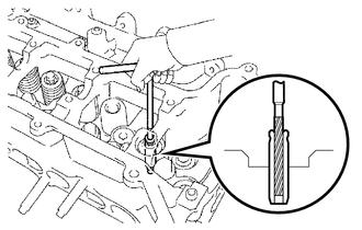
Using a reamer, ream the inside of the intake valve guide bush to the specified oil clearance between the intake valve guide bush and intake valve stem.
Standard Oil Clearance 0.025 to 0.060 mm (0.000984 to 0.00236 in.)
-
-
REPLACE EXHAUST VALVE GUIDE BUSH
-
Heat the cylinder head sub-assembly to between 80 and 100°C (176 and 212°F).
CAUTION:
Make sure not to burn yourself.
-
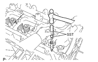
Using SST and a hammer, tap out the exhaust valve guide bush to the combustion chamber side.
- SST
- 09201-10000 ( 09201-01050 )
- 09950-70010
-
Using a caliper gauge, measure the exhaust valve guide bush bore diameter of the cylinder head sub-assembly.
Standard Exhaust Valve Guide Bush Bore Diameter 10.985 to 11.006 mm (0.4325 to 0.4333 in.) Tech Tips
-
If the exhaust valve guide bush bore diameter is as specified, install a standard exhaust valve guide bush.
-
If the exhaust valve guide bush bore diameter is not as specified, correct it to 11.035 to 11.056 mm (0.4345 to 0.4353 in.) and install the oversize exhaust valve guide bush.
Bush Size Specified Condition STD 10.985 to 11.006 mm (0.4325 to 0.4333 in.) O/S 0.05 11.035 to 11.056 mm (0.4344 to 0.4353 in.)
-
-
Heat the cylinder head sub-assembly to between 80 and 100°C (176 and 212°F).
CAUTION:
Make sure not to burn yourself.
-
Using SST and a hammer, tap in a new exhaust valve guide bush to the specified protrusion height.
- SST
- 09201-10000 ( 09201-01050 )
- 09950-70010
Standard Protrusion Height 15.9 to 16.7 mm (0.626 to 0.657 in.) -
Using a reamer, ream the inside of the exhaust valve guide bush to the specified oil clearance between the exhaust valve guide bush and exhaust valve stem.
Standard Oil Clearance 0.030 to 0.065 mm (0.00118 to 0.00256 in.)
-
-
REPLACE RING PIN
Note
It is not necessary to remove the ring pins unless they are being replaced.
-
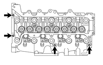
Remove the 4 ring pins indicated in the illustration.
-
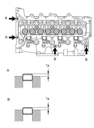
*a Protrusion Height Using a plastic hammer, tap in 4 new ring pins to the specified protrusion height.
Ring Pin Protrusion Height (A) 3.5 mm (0.138 in.) (B) 4.0 to 5.0 mm (0.157 to 0.197 in.)
-
-
REPLACE STRAIGHT PIN
Note
It is not necessary to remove the straight pin unless they are being replaced.
-
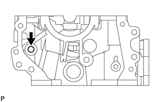
Remove the straight pin indicated in the illustration.
-
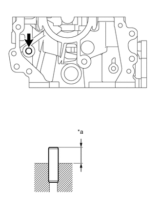
*a Protrusion Height Using a plastic hammer, tap in a new straight pin to the specified protrusion height.
Standard Protrusion Height 18.5 to 19.5 mm (0.728 to 0.768 in.)
-
-
REPLACE STUD BOLT
-
Using an E6, E8 and E10 "TORX" socket wrenches, remove the 16 stud bolts.
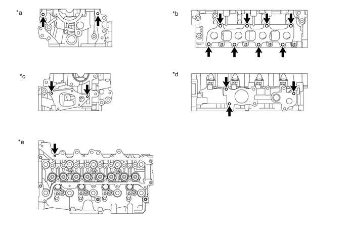
*a Front Side *b Exhaust Manifold Side *c Rear Side *d Intake Manifold Side *e Upper Side - - -
Using an E6, E8 and E10 "TORX" socket wrench, install the 16 stud bolts.
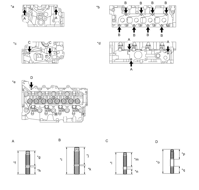
*a Front Side *b Exhaust Manifold Side *c Rear Side *d Intake Manifold Side *e Upper Side *f 42.0 mm (1.65 in.) *g 27.0 mm (1.06 in.) *h 13.0 mm (0.512 in.) *i 48.5 mm (1.91 in.) *j 31.5 mm (1.24 in.) *k 15.0 mm (0.591 in.) *l 39.0 mm (1.54 in.) *m 26.0 mm (1.02 in.) *n 9.0 mm (0.354 in.) *o 42.0 mm (1.65 in.) *p 17.0 mm (0.669 in.) *q 12.0 mm (0.472 in.) - - - Torque:
- Stud Bolt (A)
- 10 N*m { 102 kgf*cm, 7 ft.*lbf }
- Stud Bolt (B)
- 15 N*m { 153 kgf*cm, 11 ft.*lbf }
- Stud Bolt (C), (D)
- 5.0 N*m { 51 kgf*cm, 44 in.*lbf }
-