ГОЛОВКА БЛОКА ЦИЛИНДРОВ (для моделей с контроллером свечей накаливания) ПРОВЕРКА

PROCEDURE
-
INSPECT CYLINDER HEAD SUB-ASSEMBLY
-
Inspect cylinder head sub-assembly warpage.
-
Using a precision straightedge and feeler gauge, measure the warpage of the cylinder block sub-assembly side, intake air connector side and exhaust manifold side.
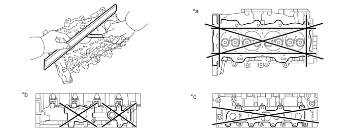
*a Cylinder Block Sub-assembly Side *b Exhaust Manifold Side *c Intake Air Connector Side - - Maximum Warpage Surface Specified Condition Cylinder Block Sub-assembly side 0.08 mm (0.00315 in.) Intake Manifold side 0.20 mm (0.00787 in.) Exhaust Manifold side 0.20 mm (0.00787 in.) If the warpage is more than the maximum, replace the cylinder head sub-assembly.
-
-
Inspect for cracks.
-
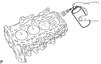
Using a dye penetrant, check the combustion chambers, intake ports, exhaust ports and contact surface of the cylinder head sub-assembly for cracks.
If cracked, replace the cylinder head sub-assembly.
-
-
-
INSPECT VALVE SEAT
-
*a Width Apply a light coat of Prussian blue to each valve face.
-
Lightly press the valve face against the valve seat.
Note
Do not rotate the valve.
-
Remove the valve from the cylinder head sub-assembly.
-
If Prussian blue appears 360° around the valve face, the valve is concentric. If not, replace the valve.
-
If Prussian blue appears 360° around the valve seat, the guide and valve face are concentric. If not, resurface the valve seat.
-
Check that the valve seat contact is in the middle of the valve face with the following width.
Standard Width for Intake 1.0 to 1.4 mm (0.0394 to 0.0551 in.) for Exhaust 1.2 to 1.6 mm (0.0472 to 0.0630 in.)
-
-
-
INSPECT CAMSHAFT OIL CLEARANCE
-
Clean the camshaft journal and camshaft bearing cap.
-
Set the camshaft to the cylinder head sub-assembly.
-
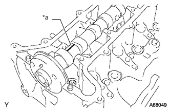
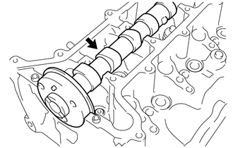
*a Plastigage Lay a strip of Plastigage across the camshaft journal.
Note
Do not turn the camshaft when measuring.
-
Install the camshaft bearing cap.
-
Remove the camshaft bearing cap.
-
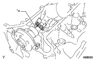
*a Plastigage Measure the Plastigage at its widest point.
Standard Oil Clearance 0.037 to 0.073 mm (0.00146 to 0.00287 in.) Maximum Oil Clearance 0.10 mm (0.00394 in.) Note
Completely remove the Plastigage after the inspection.
If the clearance is more than the maximum, replace the cylinder head sub-assembly.
-
-
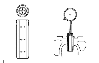
INSPECT CAMSHAFT THRUST CLEARANCE
-
Install the camshaft.
-
Install the camshaft timing sprocket to the camshaft.
-
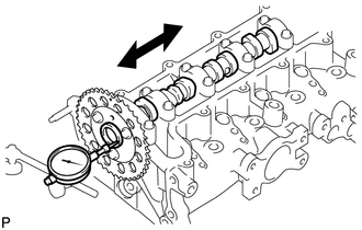
Using a dial indicator, measure the thrust clearance of the camshaft while moving the camshaft back and forth.
Standard Thrust Clearance 0.080 to 0.180 mm (0.00315 to 0.00709 in.) Maximum Thrust Clearance 0.25 mm (0.00984 in.) If the thrust clearance is more than the maximum, replace the cylinder head sub-assembly or camshaft.
-
-
INSPECT INTAKE VALVE
-
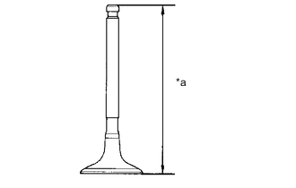
*a Overall Length Using a vernier caliper, measure the overall length of the intake valve.
Standard Overall Length 99.69 to 100.29 mm (3.9248 to 3.9484 in.) Minimum Overall Length 99.19 mm (3.9051 in.) If the overall length is less than the minimum, replace the intake valve.
-
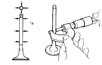
*a Valve Stem Using a micrometer, measure the valve stem diameter.
Standard Valve Stem Diameter 5.970 to 5.985 mm (0.2350 to 0.2356 in.) -
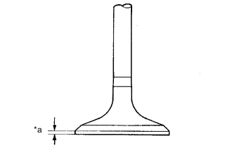
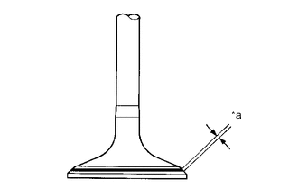
*a Margin Width Using a vernier caliper, measure the valve head margin thickness.
Standard Margin Thickness 1.2 mm (0.0472 in.) Minimum Margin Thickness 0.6 mm (0.0236 in.) If the margin width is less than the minimum, replace the intake valve.
-
-
INSPECT EXHAUST VALVE
-
*a Overall Length Using a vernier caliper, measure the overall length of the exhaust valve.
Standard Overall Length 99.39 to 99.99 mm (3.9130 to 3.9366 in.) Minimum Overall Length 98.89 mm (3.8933 in.) If the overall length is less than the minimum, replace the exhaust valve.
-

*a Valve Stem Using a micrometer, measure the valve stem diameter.
Standard Valve Stem Diameter 5.965 to 5.980 mm (0.2348 to 0.2354 in.) -
*a Margin Width Using a vernier caliper, measure the valve head margin thickness.
Standard Margin Thickness 1.5 mm (0.0591 in.) Minimum Margin Thickness 0.7 mm (0.0276 in.) If the margin width is less than the minimum, replace the exhaust valve.
-
-
INSPECT OUTER COMPRESSION SPRING
-
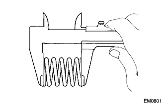
Using a vernier caliper, measure the free length of the outer compression spring.
Standard Free Length 42.80 mm (1.69 in.) -
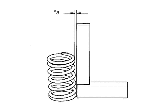
*a Deviation Using a steel square, measure the deviation of the outer compression spring.
Maximum Deviation 1.5 mm (0.0591 in.) If the deviation is more than the maximum, replace the outer compression spring.
-
-
INSPECT VALVE GUIDE BUSH OIL CLEARANCE
-
Using a caliper gauge, measure the inside diameter of the valve guide bush.
Standard Valve Guide Bush Inside Diameter 6.010 to 6.030 mm (0.2366 to 0.2374 in.) -
Subtract the valve stem diameter measurement from the inside diameter measurement of the valve guide bush.
Standard Oil Clearance Guide Bush Specified Condition Intake 0.025 to 0.060 mm (0.000984 to 0.00236 in.) Exhaust 0.030 to 0.065 mm (0.00118 to 0.00256 in.) Maximum Oil Clearance Guide Bush Specified Condition Intake 0.08 mm (0.00315 in.) Exhaust 0.10 mm (0.00394 in.) If the clearance is more than the maximum, replace the valve and valve guide bush.
-