РАСПРЕДВАЛ (для моделей с контроллером свечей накаливания) УСТАНОВКА
PROCEDURE
-
INSTALL CAMSHAFT
-
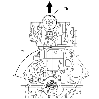
*a Key *b Knock Pin *c 75° BTDC *d Bolt Hole of Timing Chain Cover Sub-assembly 
Upper of Engine Turn the crankshaft to set the key in the 75° BTDC (aligned with the bolt hole of timing chain cover sub-assembly) position.
-
Apply engine oil to each camshaft journal portion and cam portion.
-
Install the camshaft to the cylinder head sub-assembly.
Note
-
Do not tilt the No. 1 valve rocker arm sub-assembly when installing the camshaft to the cylinder head sub-assembly.
-
Align the camshaft knock pin towards the top of the engine.
-
-
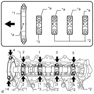
*1 No. 1 Camshaft Bearing Cap *2 No. 2 Camshaft Bearing Cap *3 No. 4 Camshaft Bearing Cap *a Front Mark Engine Front Confirm the front marks and numbers, then place the No. 1 camshaft bearing cap, 3 No. 2 camshaft bearing caps and No. 4 camshaft bearing cap on the camshaft with the front marks facing as shown in the illustration.
-
Install and uniformly tighten the 10 bolts in several steps in the order shown in the illustration.
- Torque:
- 19 N*m { 194 kgf*cm, 14 ft.*lbf }
-
-
INSTALL CHAIN SUB-ASSEMBLY
-
INSTALL NO. 1 CHAIN VIBRATION DAMPER
-
INSTALL CHAIN TENSIONER SLIPPER
-
INSTALL NO. 1 CHAIN TENSIONER ASSEMBLY
-
INSTALL TIMING CHAIN COVER OIL SEAL
-
INSTALL TIMING CHAIN COVER SUB-ASSEMBLY
-
CONNECT WATER INLET HOSE LH
-
Connect the water inlet hose LH to the water inlet and slide the hose clip to secure it.
Tech Tips
The clip on the water inlet side can be installed with any orientation, as long as it does not contact any of the surrounding parts.
-
-
INSTALL CRANKSHAFT DAMPER SUB-ASSEMBLY
-
INSTALL CAMSHAFT POSITION SENSOR
-
INSTALL NO. 2 TIMING CHAIN COVER
-
INSTALL ENGINE MOUNTING BRACKET RH
-
CHECK VALVE CLEARANCE
-
ADJUST VALVE CLEARANCE
-
INSTALL CYLINDER HEAD COVER SUB-ASSEMBLY
-
INSTALL V-RIBBED BELT TENSIONER ASSEMBLY
-
INSTALL VACUUM PUMP ASSEMBLY
-
INSTALL WATER BY-PASS PIPE SUB-ASSEMBLY
-
Install a new O-ring to the water by-pass pipe sub-assembly.
Note
Apply coolant around the water by-pass pipe O-ring groove of the water inlet housing before installing the water by-pass pipe sub-assembly.
-
Install the water by-pass pipe sub-assembly to the No. 2 turbocharger stay, cylinder head sub-assembly, cylinder block sub-assembly and water inlet housing with the 3 bolts.
- Torque:
- 9.0 N*m { 92 kgf*cm, 80 in.*lbf }
-
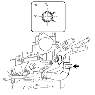
*a View (A) *b RH of Engine *c Front of Engine Connect the oil cooler hose to the water by-pass pipe sub-assembly and slide the hose clip to secure it.
-
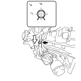
*a View (A) *b Top of Engine *c Front of Engine Connect the water by-pass hose to the tube connector and slide the hose clip to secure it.
-
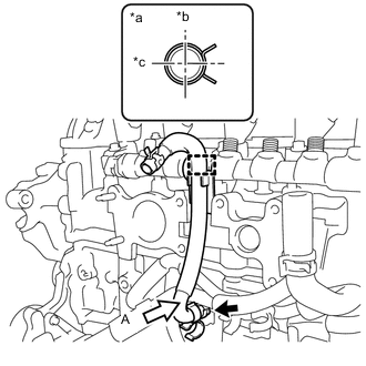
*a View (A) *b Front of Engine *c LH of Engine Connect the No. 6 water by-pass hose to the water by-pass pipe sub-assembly and slide the hose clip to secure it.
-
-
INSTALL NO. 4 WATER BY-PASS HOSE
-
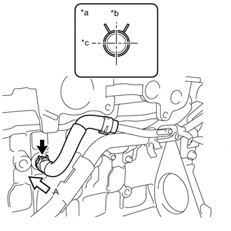
*a View (A) *b Top of Engine *c Front of Engine Install the No. 4 water by-pass hose to the water inlet pipe and slide the hose clip to secure it.
Note
Perform the installation with the hose clip at the correct angle.
-
Engage the clamp to connect the No. 4 water by-pass hose to the common rail assembly.
-
-
INSTALL NO. 2 OIL COOLER HOSE
-
INSTALL SUPPLY PUMP ASSEMBLY
-
INSTALL FUEL PUMP PROTECTOR
-
INSTALL NO. 2 NOZZLE LEAKAGE PIPE
-
CONNECT NO. 2 FUEL HOSE
-
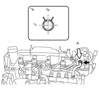
*a View (A) *b Top of Engine *c Rear of Engine Connect the No. 2 fuel hose to the No. 2 nozzle leakage pipe and slide the hose clip to secure it.
-
-
CONNECT NO. 1 FUEL HOSE
-
INSTALL FUEL INLET PIPE SUB-ASSEMBLY
-
CONNECT NOZZLE LEAKAGE PIPE ASSEMBLY
-
INSTALL INTAKE AIR CONNECTOR WITH DIESEL THROTTLE BODY
-
INSTALL ENGINE OIL LEVEL DIPSTICK GUIDE
-
INSTALL ENGINE OIL LEVEL DIPSTICK
-
INSTALL EGR VALVE (ELECTRIC EGR CONTROL VALVE ASSEMBLY)
-
INSTALL HARNESS BRACKET (for LHD)
-
INSTALL HARNESS BRACKET (for RHD)
-
INSTALL NO. 1 EGR COOLER BRACKET
-
INSTALL EGR WITH COOLER PIPE ASSEMBLY
-
INSTALL GENERATOR BRACKET
-
INSTALL GENERATOR ASSEMBLY
-
INSTALL ENGINE COVER BRACKET
-
REMOVE ENGINE FROM ENGINE STAND