СИСТЕМА ECD, Diagnostic DTC:P0617
| DTC Code | DTC Name |
|---|---|
| P0617 | Starter Relay Circuit High |
DESCRIPTION
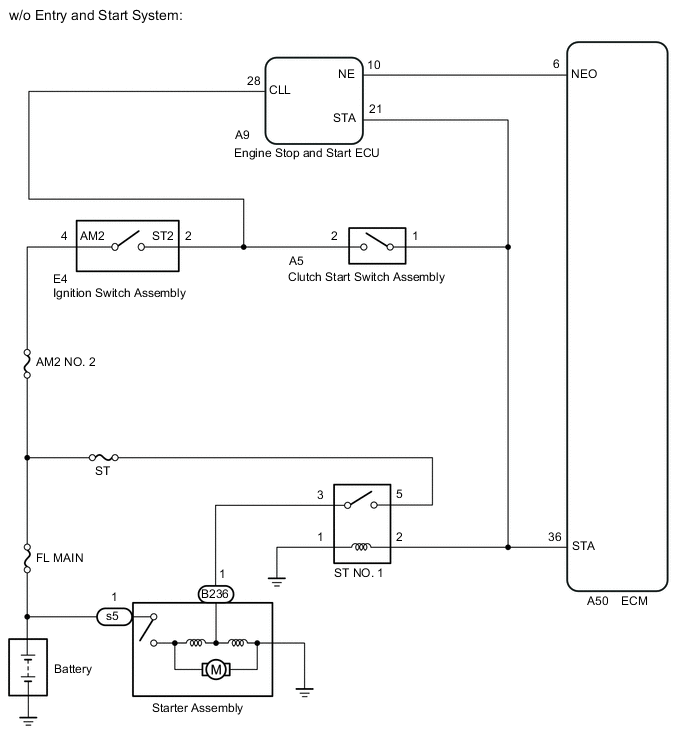
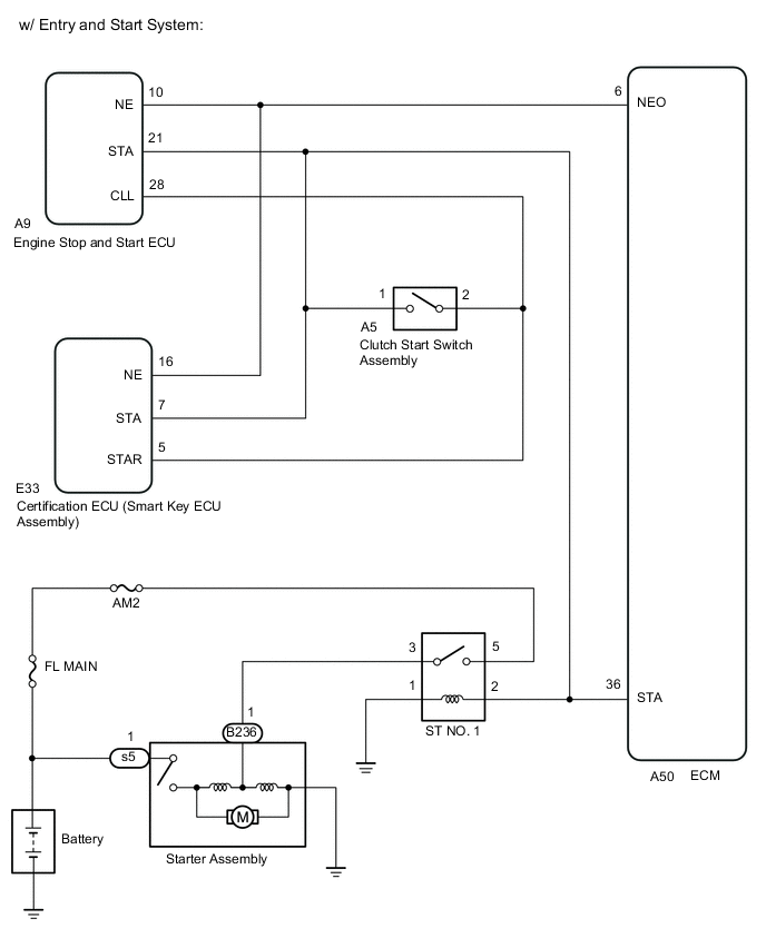
While the engine is being cranked, the Starter Control (STA) signal is also sent to terminal STA of the ECM. The STA signal is used to increase the fuel injection volume mainly when starting the engine. If the ECM detects the Starter Control (STA) signal while the vehicle is being driven, this DTC is stored.
| DTC No. | Detection Item | DTC Detection Condition | Trouble Area | MIL | Memory |
|---|---|---|---|---|---|
| P0617 | Starter Relay Circuit High | STA signal is being input to ECM regardless of whether vehicle is in motion. (1 trip detection logic) |
|
Comes on | DTC stored |
| DTC No. | Data List |
|---|---|
| P0617 | Starter Signal |
WIRING DIAGRAM
CAUTION / NOTICE / HINT
Note
-
When replacing the ECM, the ECM needs registration and initialization.
-
Inspect the fuses for circuits related to this system before performing the following inspection procedure.
Tech Tips
-
The following troubleshooting process is based on the premise that the engine can crank normally. If the engine does not crank, proceed to Problem Symptoms Table.
-
If this DTC is output, inspect the starter.
-
Read freeze frame data using the GTS. Freeze frame data records the engine condition when malfunctions are detected. When troubleshooting, freeze frame data can help determine if the vehicle was moving or stationary, if the engine was warmed up or not, and other data from the time the malfunction occurred.
PROCEDURE
-
READ VALUE USING GTS (STARTER SIGNAL)
-
Connect the GTS to the DLC3.
-
Turn the ignition switch to ON and turn the GTS on.
-
Enter the following menus: Powertrain / Engine and ECT / Data List / Starter Signal.
Powertrain > Engine and ECT > Data ListTester Display Starter Signal -
Read the value displayed on the GTS when the ignition switch is turned to ON.
OK Ignition Switch Positions Starter Signal ON OFF START ON Result Result Proceed to OK A NG (w/ Entry and Start System) B NG (w/o Entry and Start System) C
A 
GO TO STEP 8 Click here
C
INSPECT IGNITION SWITCH ASSEMBLY Click here
B 
-
-
CHECK HARNESS AND CONNECTOR
-
Disconnect the certification ECU (smart key ECU assembly) connector.
-
Disconnect the ECM connector.
-
Remove the ST NO. 1 relay from the engine room relay block and junction block.
-
Measure the resistance according to the value(s) in the table below.
Standard Resistance Tester Connection Condition Specified Condition E33-7 (STA) or A50-36 (STA) - Body ground and other terminals Always 10 kΩ or higher Result Proceed to OK NG
OK
GO TO STEP 5 Click here
NG
GO TO STEP 6 Click here
-
-
INSPECT IGNITION SWITCH ASSEMBLY
-
Inspect the ignition switch assembly.
Result Proceed to OK NG
NG
REPLACE IGNITION SWITCH ASSEMBLY Click here
OK
-
-
CHECK HARNESS AND CONNECTOR
-
Disconnect the ignition switch connector.
-
Disconnect the ECM connector.
-
Remove the ST NO. 1 relay from the engine room relay block and junction block.
-
Measure the resistance according to the value(s) in the table below.
Standard Resistance Tester Connection Condition Specified Condition E4-2 (ST2) or A50-36 (STA) - Body ground and other terminals Always 10 kΩ or higher Result Proceed to OK NG
NG
REPAIR OR REPLACE HARNESS OR CONNECTOR Click here
OK
-
-
REPLACE ECM
-
Replace the ECM.
Result Proceed to NEXT
NEXT
GO TO STEP 8 Click here
-
-
REPAIR OR REPLACE HARNESS OR CONNECTOR
-
Repair or replace the harness or connector.
Result Proceed to NEXT
NEXT
GO TO STEP 8 Click here
-
-
REPLACE IGNITION SWITCH ASSEMBLY
-
Replace the ignition switch assembly.
Result Proceed to NEXT
NEXT
-
-
CONFIRM WHETHER MALFUNCTION HAS BEEN SUCCESSFULLY REPAIRED
-
Connect the GTS to the DLC3.
-
Turn the ignition switch to ON and turn the GTS on.
-
Clear the DTCs.
Powertrain > Engine and ECT > Clear DTCs -
Turn the ignition switch off and wait for 60 seconds or more [A].
-
Perform road test [B].
-
Repeat [A] and [B] for the number of trips detected.
-
Enter the following menus: Powertrain / Engine and ECT / Trouble Codes.
Powertrain > Engine and ECT > Trouble Codes -
Confirm that the DTC is not output again.
Result Proceed to NEXT
NEXT 
END
-