PROCEDURE
- Click here
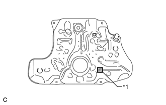
INSTALL FUEL TANK MAIN TUBE SUB-ASSEMBLY
-
*1 Fuel Tank Main Tube Sub-assembly Install the fuel tank main tube sub-assembly to the fuel tank assembly.
-
- Click here
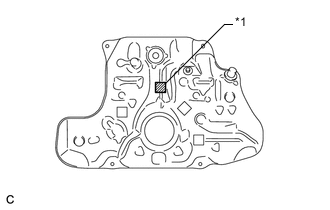
INSTALL FUEL RETURN TUBE SUB-ASSEMBLY
-
*1 Fuel Return Tube Sub-assembly Install the fuel return tube sub-assembly to the fuel tank assembly.
-
- Click here
INSTALL NO. 2 FUEL TANK CUSHION (w/ No. 2 Fuel Tank Cushion)
-
*1 No. 2 Fuel Tank Cushion Install a new No. 2 fuel tank cushion as shown in the illustration.
-
- Click here
INSTALL NO. 1 FUEL TANK CUSHION
-
*1 No. 1 Fuel Tank Cushion Install a new No. 1 fuel tank cushion as shown in the illustration.
-
- Click here
INSTALL FUEL TANK ASSEMBLY
-
Support the fuel tank assembly using an engine lifter.
-
Raise the engine lifter, then install the fuel tank assembly to the vehicle.
Note:
-
Do not drop the fuel tank assembly.
-
When installing the fuel tank assembly, tilt it slightly to prevent it from interfering with the suspension arm or other surrounding parts.
-
-
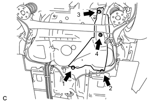
Temporarily install the fuel tank assembly with the 4 bolts.
-
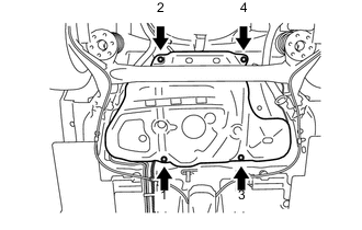
Tighten the fuel tank assembly with the 4 bolts in the order shown in the illustration.
39.2 N*m 400 kgf*cm 29 ft.*lbf -
Connect the parking brake cable assembly with the 2 bolts.
6.0 N*m 61 kgf*cm 53 in.*lbf
-
- Click here
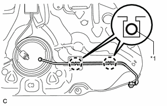
CONNECT FUEL TANK MAIN TUBE SUB-ASSEMBLY
-
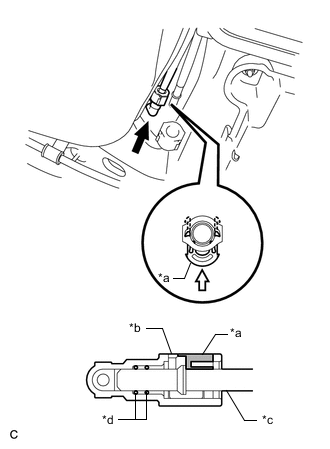
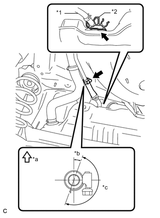
*a Retainer *b Fuel Tube Connector *c Fuel Pipe *d O-ring 
Push 
Push up Push in the fuel tube connector to the fuel pipe and push up the retainer so that the claws engage.
Note:
-
Check that there are no scratches or foreign matter around the connecting parts of the fuel tube connector and fuel pipe before performing this work.
-
After connecting the fuel tube connector, check that the fuel tube connector is securely connected by pulling on the fuel tube connector.
-
-
- Click here
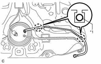
CONNECT FUEL RETURN TUBE SUB-ASSEMBLY
-
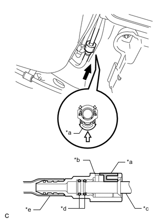
*a Retainer *b Fuel Tube Connector *c Fuel Pipe *d O-ring *e Nylon Tube Push Push up Push in the fuel tube connector to the fuel pipe and push up the retainer so that the claws engage.
Note:
-
Check that there are no scratches or foreign matter around the connecting parts of the fuel tube connector and fuel pipe before performing this work.
-
After connecting the fuel tube connector, check that the fuel tube connector is securely connected by pulling on the fuel tube connector.
-
-
- Click here
CONNECT FUEL TANK TO FILLER PIPE HOSE
-
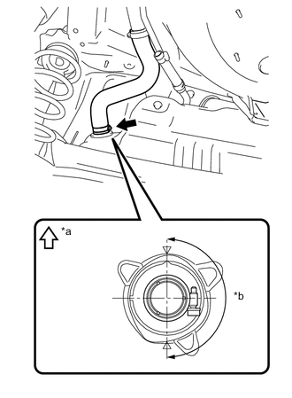
*a Upper *b 180° Connect the fuel tank to filler pipe hose to the fuel tank assembly, and tighten the clamp as shown in the illustration.
Note:Be careful of the installation angle of the clamp.
-
- Click here
CONNECT FUEL TANK BREATHER TUBE
-
*1 Fuel Tank Breather Tube *2 Evaporation Vent Tube Clamp *a Upper *b 20° *c 180°(Clamp Area) Connect the fuel tank breather tube to the fuel tank filler pipe sub-assembly, and tighten the clamp as shown in the illustration.
Note:After connecting the fuel tank breather tube, check that the evaporation vent tube clamp is securely connected to the fuel tank assembly.
-
- Click here
INSTALL NO. 1 FUEL TANK PROTECTOR
-
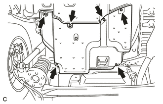
Temporarily install the No. 1 fuel tank protector with the 3 bolts and nut.
-
Tighten the No. 1 fuel tank protector with the 3 bolts and nut in the order shown in the illustration.
5.5 N*m 56 kgf*cm 49 in.*lbf
-
- Click here
INSTALL CENTER EXHAUST PIPE ASSEMBLY
- Click here
INSTALL REAR NO. 1 FLOOR UNDER COVER
-
Install the rear No. 1 floor under cover with the grommet.
-
Install the 4 clips and nut.
-
- Click here
INSTALL REAR FLOOR SIDE MEMBER BRACE SUB-ASSEMBLY
- Click here
INSTALL REAR FLOOR SIDE MEMBER COVER LH
- Click here
INSTALL REAR FLOOR SIDE MEMBER COVER RH
- Click here
INSTALL FUEL TANK VENT TUBE SUB-ASSEMBLY
- Click here
ADD FUEL
- Click here
INSPECT FOR EXHAUST GAS LEAK