КОРПУС ДРОССЕЛЬНОЙ ЗАСЛОНКИ ДИЗЕЛЬНОГО ДВИГАТЕЛЯ УСТАНОВКА
PROCEDURE
-
INSTALL DIESEL THROTTLE BODY ASSEMBLY (w/ Glow Plug Controller)
-
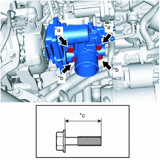
*a Bolt Length: 50 mm (1.97 in.) *b Bolt Length: 25 mm (0.984 in.) *c Bolt Length Install a new venturi gasket and the diesel throttle body assembly to the intake air connector with the 4 bolts as shown in the illustration.
- Torque:
- 8.5 N*m { 87 kgf*cm, 75 in.*lbf }
Note
If the diesel throttle body assembly has been struck or dropped, replace it.
-
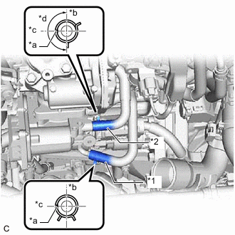
*1 No. 3 Water By-pass Hose *2 No. 5 Water By-pass Hose *a Paint Mark *b Up *c LH Side *d Claws of clip should not enter this area Connect the No. 3 water by-pass hose and No. 5 water by-pass hose to the diesel throttle body assembly in the positions shown in the illustration, and slide the 2 clips to secure them.
-
Engage the clamp to install the engine wire.
-
Install the bolt.
- Torque:
- 8.0 N*m { 82 kgf*cm, 71 in.*lbf }
-
Connect the generator assembly connector and diesel throttle body assembly connector.
-
-
INSTALL DIESEL THROTTLE BODY ASSEMBLY (w/o Glow Plug Controller)
-
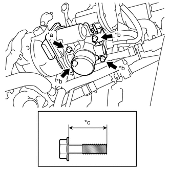
*a Bolt Length: 50 mm (1.97 in.) *b Bolt Length: 25 mm (0.984 in.) *c Bolt Length Install a new venturi gasket, the diesel throttle body assembly and wire harness bracket to the intake air connector with the 4 bolts as shown in the illustration.
- Torque:
- 8.5 N*m { 87 kgf*cm, 75 in.*lbf }
Note
If the diesel throttle body assembly has been struck or dropped, replace it.
-
Engage the clamp to install the engine wire.
-
Install the nut.
- Torque:
- 8.0 N*m { 82 kgf*cm, 71 in.*lbf }
-
Connect the generator assembly connector and diesel throttle body assembly connector.
-
-
INSTALL NO. 2 AIR TUBE
-
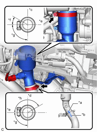
*a Stopper *b Paint Mark *c Rear of Vehicle *d Front of Vehicle *e LH Side *f 30° *g 90° *h 150° Install the No. 2 air tube and tighten the 2 hose clamps in the positions shown in the illustration.
Tech Tips
Align the stopper on the No. 2 air tube with paint mark on the No. 3 air hose.
-
Install the 2 bolts.
- Torque:
- 10 N*m { 102 kgf*cm, 7 ft.*lbf }
-
Connect the intake air temperature sensor connector.
-
-
INSTALL INTERCOOLER AIR HOSE
-
w/ Glow Plug Controller:
-
w/o Glow Plug Controller:
-
-
INSTALL NO. 1 ENGINE COVER (w/ No. 1 Engine Cover)
-
w/ Glow Plug Controller:
-
w/o Glow Plug Controller:
-
-
INSTALL NO. 1 ENGINE UNDER COVER
-
w/ Glow Plug Controller:
-
for Full Cover Type:
-
for Half Cover Type:
-
w/o Glow Plug Controller:
-
for Full Cover Type:
-
for Half Cover Type:
-
-
PERFORM INITIALIZATION
-
w/ Glow Plug Controller:
-
w/o Glow Plug Controller:
-